

HydraRaptor: Suppression. Some time ago I blogged that the GM3 gearmotor generates a lot of RFI, which was interfering with TV reception in our house and corrupting I2C comms on HydraRaptor.
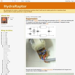
I designed a simple suppressor that fixed the problem, details here. Recently Zach Smith designed a nice little PCB version of it and produced a kit. He gave me a sample to test. How to Build a Robot Tutorials - Society of Robots. Introduction to Mechanical Engineering Theory, Dynamics While statics is the study of structures at a fixed point in time, dynamics is the study of structures over a period of time.
Basically statics studies things that dont move, while dynamics studies things that do. Statics is concerned with moments, forces, stresses, torque, pressure, etc. Dynamics is concerned with displacement, velocity, acceleration, momentum, etc. If you want to calculate and/or optimize forces generated or required for a moving robot, this tutorial has the basics that you will need to understand. It is highly recommended you read the statics tutorial first as this tutorial will build off of it. How to Build a Robot Tutorials - Society of Robots. The Robot Encoder - What is it?

The encoder is a sensor attached to a rotating object (such as a wheel or motor) to measure rotation. By measuring rotation your robot can do things such as determine displacement, velocity, acceleration, or the angle of a rotating sensor. Køb Bøsninger låsebøsninger TOLLOK CLAMP 6MM Lenze TLK110 6X14 online fra RS. Set Screw Hubs. These hubs use a 3/32” Hex Key(click here) 5-40 Pan Head Screws(click here) 5-40 Socket Head Screws(click here)
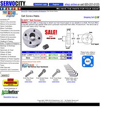
Rad, Welle, Nabe Verbindung. DC motor control with PID. 0.770" Set Screw Hubs. Set screw hubs offer a cheap way to attach hub mount gears or wheels to a shaft.

Arduino With L298N Based Dual Motor Controller. The ControllerA motor controller is a device that serves to govern in some predetermined manner the performance of an electric motor.
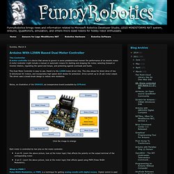
A motor controller might include a manual or automatic means for starting and stopping the motor, selecting forward or reverse rotation, regulating the speed and torque, and protecting against overloads and faults. This Dual Motor Controller is easy to use, thank's to the L298N motor driver chip. This chip allows for direct drive of two bi-directional DC motors, and incorporates high-speed short diodes for protection. Drive current up to 2A per motor output. The driver uses a broad-brush design to reduce wire resistance.Below, an illustration of the DRI0002, an inexpensive board avalaible by DFRobot.
Click the image to enlarge Each motor is controlled by two pins on the motor controller: A pin M, (zoom the above picture, look at the motor logic) that affects the polarity on the output terminal of the corresponding motor. Click the image to enlarge. ALF - Analog Line Follower. Hi, I am ALF, short for Analog Line Follower. I am not an alien, i do not eat cats and i am pretty much earth based, more precise silicon based ;-) Ok, this was the self introduction of ALF. Since some time I am working on a PCB based on a friends circuit plan for an analog line follower. Now the prototype is finished and working (well, the end of the video is staged to give you something to complain ;-) ) There is not much to say, I also do not have much pictures of the build but I will add more later when I am going to adjust the accuracy.
This is the circuit plan my friend designed. The PCB was changed some times to find the best way to put all the components on it, balance it and still make it easy to build. As you can see on the PCB, ALF (or better said the components for at least 100 ALF's) is going to Berlin to the Campus Party and hopefully will be adopted by a lot of people. Attaching the gear motors, well, either double side tape or hotglue, what do you think? UPDATE July 18: Www.ti.com/lit/an/slua137/slua137.pdf. Making a FET "H" bridge (revised) One thing most robots need is the ability to control motors. This circuit will work from 7.2V to 15V with PWM frequencies up to 25KHz and drive motors with a stall current of 20A. Features include not only speed and direction but it also has electronic braking, fuse protection and current sensing. Click on the schematic for a larger image. I have now attached some files with information on current shunts and heatsink calculations.
As this schematic has been updated you may need to reset your browser cache to see the new schematic. I finally had time to build and test this circuit thoroughly using a DSO (Digital Sampling Oscilloscope) to check that it all worked properly. BJT H-bridge Circuit Details. I really like this H-bridge for a number of reasons, not the least of which is that if you buy your parts in quantities of 1, all the parts cost under $5 (excluding tax & shipping of course) for a 1 - 5 amp capable H-bridge. This keeps the final circuit in the "cheap" category which was one of the design parameters we're optimizing for. The complete schematic for the bridge is shown below. The fast recovery diodes (shown in light blue) are optional when you are using the TIP102/107 as those transistors have a diode built into them. However you can include them for greater protection at higher currents and still keep the cost at $5 per bridge.
In the table below is a parts list, with prices from November of 2003, using part numbers from Mouser Electronics. Table 1) Parts List for the Simple H-Bridge In the previous section we discussed the individual parts of this design, here they are gathered together in a single circuit. Processor Interface. Chuck's Robotics Notebook. Introduction A number of web sites talk about H-bridges, they are a topic of great discussion in robotics clubs and they are the bane of many robotics hobbyists. I periodically chime in on discussions about them, and while not an expert by a long shot I've built a few over the years.
Further, they were one of my personal stumbling blocks when I was first getting into robotics. This section of the notebook is devoted to the theory and practice of building H-bridges for controlling brushed DC motors (the most common kind you will find in hobby robotics ...) I've got an image of one below with both as a unit and "expanded" in an exploded view. Basic Theory Let's start with the name, H-bridge. Of course the letter H doesn't have the top and bottom joined together, but hopefully the picture is clear. The key fact to note is that there are, in theory, four switching elements within the bridge. Technology Circuits - Practical H-Bridge Current Monitor Offers Fault Detection and Bidirectional Load Information. High Current, High Voltage H-BRIDGE Information.
A better MOSFET H Bridge Schematic for your online MBA studies - The Using MOSFETS Website.