

High Voltage Switch Mode Power Supply (SMPS)/Boost Converter for Nixie Tubes. Www.ecircuitslab.com/2011/07/to-drive-nixie-tubes-or-neon-lamps-you.html. To drive nixie tubes or neon lamps you need a DC power supply of around 170 volts for consistent and fast tube striking.
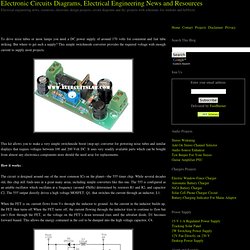
But where to get such a supply? This simple switchmode converter provides the required voltage with enough current to supply most projects. This kit allows you to make a very simple switchmode boost (step-up) converter for powering nixie tubes and similar displays that require voltages between 100 and 200 Volt DC. It uses very readily available parts which can be bought from almost any electronics components store should the need arise for replacements. How it works : The circuit is designed around one of the most common ICs on the planet—the 555 timer chip. When the FET is on, current flows from V+ through the inductor to ground.
This cycle continues until the voltage across C4 reaches a value set by trimpot VR1. Building it : The smoke test : Parts : Warning! Dave Cooper's Nixie Tube Page. Nixie Tube Collection (T) - www.jb-electronics.de. Nixie Displays. They have a very interesting decoder design using neon lamps (hidden under the black lid just behind the Nixie tube).
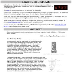
HP made a decade counter/display board where the counter flip-flops were made from pairs of transistors in the conventional way (8 transistors on the board). These were controlled with diodes to count in 1242 (not 1248) BCD code. The outputs of these counters drove 8 neon bulbs, and by varying the bias applied, the state of the counter could be latched in the bulbs (that's why this is relevant here). How to drive nixie tubes. If you want to build a nixie display for your project, you'll have to know how use and drive nixie tubes. Discussed here are basic and multiplexed use. There are a number of schematics to illustrate it all.
How it works. Unting & display tubes. Dekatrons Electron-beam tubes Filament indicators Neon 7-segment tubes Nixie Tubes These neon-filled numeric displays, also known as 'numicators', consist of an outer mesh anode, with ten cathodes (or 11/12 with decimal point/points) shaped to form numbers.
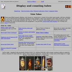
They were popular in the 1960s and early 70s when the first logic ICs became available, the 7441 or 74141 TTL devices often being used as a driver, and can still sometimes be seen in old electronic test equipment. I can provide custom-built nixie displays for TV/Film use - please email if interested. Left to right : Standard tube (probably Mullard ZM1175), Mullard ZM1080, with orange coating on glass to improve colour, Unusual ITT tube with sine, spiral, minus and plus indicators, 'stretch NE-2' lamp used as first digit in 3½ digit display, Valvo/Ultron ZM1042 1.3" high digit.
Un horologe à tubes Nixie, version 1.0 - Davide Bucci. Introduction Les tubes nixie ont été introduits dans le marché à partir des années cinquante du siècle dernier.
Il s'agit en gros d'une lampe néon à décharge dans laquelle on retrouve une anode et plusieurs cathodes, ces derniers ayant la forme des chiffres à montrer. En polarisant l'anode et une des cathodes avec une tension supérieure à une centaine de volts, on obtiendra une décharge de couleur jaune/orange autour de la cathode sélectionnée. En démontant un vieux multimètre numérique désormais hors service, j'ai réussi à récupérer quelque nixies de type TAF1317A et, avec un ami, on s'est mis à étudier une façon de les réutiliser. Sur Internet, on trouve beaucoup de matériel sur ce type d'afficheurs, qui sont caractérisé par un certain charme d'antan.
Si ce projet vous plaît, lisez aussi la page Un horloge à nixie, version 2.1 sur ce même site. Le circuit Le convertisseur est basé sur un oscillateur à relaxation construit autour d'une moitié d'un NE556 (un NE555 suffirait). Le firmware. Www.tubeclock.com/manual.pdf. Nixie Clock. Www.pvelectronics.co.uk/kits/LTC1040/LTC1040_v1.pdf. Tube-in-a-Tube Clock. WARNING!
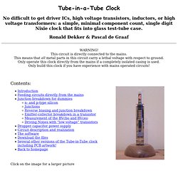
This circuit is directly connected to the mains. This means that all metal parts in this circuit carry a lethal voltage with respect to ground. Only operate this clock directly from the mains if a completely isolated casing is used. Only build this clock if you have experience with mains operated circuits! Introduction When Pascal de Graaf, a colleague of mine, and I had to make a business to Hamburg some time ago, we had plenty of time to discuss a mutual interest: nixie clocks. I did not agree with him.
This clock first of all demonstrates that it is possible to use standard, low-voltage, general puspose, small-signal transistors like the BC550, as nixie drivers. The high voltage supply for the nixie in this clock is directly taken from the mains. By minimizing the power consumption of the controller circuit, it additionally was possible to feed the low-voltage controller circuit directly from main, without the need for a transformer! Feeding circuits directly from the mains.