
Digital Compass. Application notes for robotics, motor control, Arduino, BASIC Stamp. Autonomous car – navigation. As part of my autonomous car project ( I need to make the car turn towards its destination.

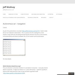
This is a picture of a PLC reading the current location using a GPS and calculating the bearing (the direction from the current location to the destination) and distance between the current location and the destination. For more details, Which direction should the car go? The car’s direction is a function of where it is and where it should be. I manually entered where it should be. Here is a picture of the car’s GPS sensor readings matching my phone’s GPS sensor readings. Steering to a Heading - Wayne's Tinkering Page. Human's managed to discover magnetic navigation, in the form of the compass, sometime around the 12th century.

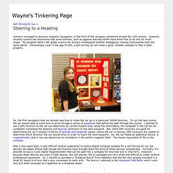
However, recently science has discovered that some animals, such as pigeons and sea turtles have know how to do this for much longer. My daughter Belle's 8th grade science fair project investigated whether Madagascar Hissing Cockroaches have the same ability. Interestingly, even in the age of GPS, a self driving car will need a good, reliable compass to help it steer properly. So, the first navigation task we tackled was how to make the car go in a particular NSEW direction. To run the race course, the car would need to know how to drive through a series of waypoints that define the path through the course. Only a few years back, it was difficult (and/or expensive) to build a digital compass suitable for a self driving RC car, but devices like Apple iPhone that include this function have brought down the price of these devices considerably. #include <Wire.h> Fundamentals of a GPS guided vehicle.
So you are interested in building a GPS guided vehicle? Well this is not for the beginner. This walk through does not hold your hand. I am expecting that you know things about motor drivers, micro controllers, and general electronics. Its a lot i have to cover and so some things i must cover more than others that you should already know. Also read: You will notice there are now 2 setups. What would be needed: (short list basic setup) GPS CompassVehicle ( you might want one that can drive on grass and cement)Micro Controller (in this case a Arduino.
What would be needed: (short list better setup) Fundamentals of a GPS guided vehicle. HMC5883L Compass Tutorial with Arduino Library - Tutorials - Love Electronics. Using a magnetometer can be a little tricky, especially if your unsure about the formulas to use to get the correct bearing and when other magnetic objects are interfering with your signal. We've created a library for our HMC5883L Breakout Board , which will also be compatible with other HMC5883L breakout boards made by other manufacturers. Join us whilst we cover the following: Understand what is a magnetometer and how they work. Introduce the HMC5883L Arduino Library Explain how to extract data from the HMC5883L. Explain how to calculate a bearing from this data. How do compasses work? Firstly an introduction, a (standard handheld) compass works by aligning itself to the earths magnetic field.
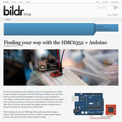
Our magnetometer uses these magnetic fields, however it doesn't pull on a little needle inside it! How do we use one? Okay, so now we know how to use one, the first step is to get some data out of our compass. Once you have the library installed start your Arduino IDE and we can get coding. Finding your way with the HMC6352. Ever look into getting yourself a digital compass, but stopped because of this or that?

Or maybe you bought one of the HMC6352 modules from sparkfun because it said it was drop dead simple, but never got around to getting it to work. What ever the reason, I want to let you know, the HMC6352 is very simple, more so than an analog one in many ways. But simple does not mean easy, it is after all an I2C device, and no matter how simple, getting a reading from it is always the hardest part. Well never fear, bildr is here.
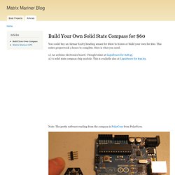
When running correctly, the HMC6352 will actually repost the heading in degrees. So, without further ado here is some code to get it working. Hooking it up When hooking up an I2C device to your arduino, all you need to know is that I2C is a 2-wire serial connection, SDA (Data) and SCL (clock) – On your arduino (everything but the mega) SDA is on analog input pin 4, and SCL is on analog pin 5. Sort comings of all digital compasses. Build Your Own Solid State Compass for $60. You could buy an Airmar h2183 heading sensor for $600 to $1000 or build your own for $60.

This entire project took 2 hours to complete. Here is what you need. Note: The pretty software reading from the compass is PolarCom from PolarNavy. Step 1: Solder together the header. Step 2: Push the sensor into the analog connector as shown. Step 3: Download and install the arduino development IDE software Linux, Mac or Windows: HMC6352 Digital Compass.