
Turnigy Accucel-6 50W 6A Balancer/Charger w/ accessories. RC Switch. Radio Controlled Switch 6 Apr 07 - Part List added.
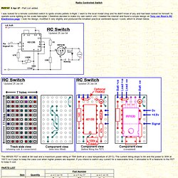
I was looked for a remote controlled switch to ignite smoke pellets in-flight. I went to the local model shop and he didn't know of any and had been looked for himself, to operate some lighting on his scale helicopter. I therefore decided to make my own switch unit. I trawled the internet and found a simple design on Tony van Roon's RC Electronics page. The IRF630 FET is rated at 9A load and a maximum power rating of 75W (both at a case temperature of 25°C) . * Available from a local model shop [Plans & Designs Page] Radio Control Switch. V1.04 2-Jan-2002 Testing status: Simulated Introduction This circuit takes the output of a radio control receiver channel, and drives a load on or off dependant upon the value on that channel.
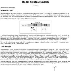
Generally, a channel can transmit a range of values, and a sercvo is used to position a motor dependant on the value sent over that channel. However, for applications such as a weapon, a simple on/off action is all that is required. Let's first have a look at the output signal of the radio receiver: A positive-going pulse is sent at regular intervals, at most every 30ms although some manufacturers have a maximum of 20ms between pulses. We want the output of our circuit to be OFF when the received pulse width is less than 1.5ms, and ON when it is greater than 1.5ms (or vice versa, it doesn't really matter). Technobots - Electronic & Mechanical Components. Turnigy Accucel-8 150W 7A Balancer/Charger (UK Warehouse) Model Radio Control electronic Circuits.
MODEL RADIO CONTROL HISTORY AND TECHNICAL INFORMATION by Terry Tippett and David Caudrey.

MANY THANKS for technical input from Dave McQue, Mike Hawkins, Barrie Allen, Mohamed Shiraz Kaleel, Alan Pratt, George Beeler, Malcolm Perry, Ron Jay, Peter Keirle, Peter Allen, Nicholas Ingle, dave1993, Randal Munroe, David Coles, Peter Gascoine. Barry Lennox, Derek Round, THE NORCIM WEBSITE……a collection of technical data and history of model radio control systems. Please enjoy! Private sale. Webra, American sparkies also a five cylinder radial motor. Contact Dave direct for details….davearmitage01 at gmail dot com (please allow a possible several days for reply). WEBSITE. well during the early 1970s, a radio control company called MICRON was started by the founders, Terry and Ada Tippett. In an attempt to provide Hints, Tips and advice regarding R/C kit building, the NORCIM WEBSITE was born. Terry Tippett and David Caudrey now run the NORCIM WEBSITE.
Recent Visitor Map by Statcounter.com 03/04/14. Solent Radio Control Model Boat Club. Introduction If you build a dual switch, you can choose to have the two switches both assigned to the same input channel (eg to actuate both the relays at points on the left/right function - or you can assign the switches to work on two independent channels (eg the transmitter on/off channels 5/6 controlled by toggle switches) On the desired R/C channel of the receiver a "Y" lead must be fitted such that the receiver feeds both the original servo PLUS this circuit.
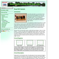
Next, simply adjust the potentiometer(s) until the relay(s) pull in at the desired transmitter stick position(s) - the LED(s) will indicate the relay(s) are energised if you can't hear them click. The circuit's relay contacts are then wired up as normal to invoke the desired auxiliary functions - eg a light, a sound, a pump . . . . . Moving a stick on the transmitter causes a variable width pulse between 1 mSec to 2 mSec (neutral = 1.5 mSec) to be output from the appropriate receiver channel. Circuit Diagrams Circuit Description. RC (Remote Control) Switch Circuit Diagram. Posted Apr 18, 2013 at 3:06 pm It is sometimes necessary for an RC (remote control) model to contain some kind of switching functionality.
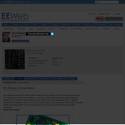
Some things that come to mind are lights on a model boat, or the folding away of the undercarriage of an aeroplane, etc. A standard solution employs a servo, which then actually operates the switch. Separate modules are also available, which may or may not contain a relay. A device with such functionality is eminently suitable for building yourself. Picture of the project: RC Switch Circuit The servo signal, which consists of pulses from 1 to 2 ms duration, depending on the desired position, enters the circuit via pin 1 of connector K1.
A standard version (such as the NE555) works just as well, but this IC draws an unnecessarily high current, while we strive to keep the current consumption as low as possible in the model. Circuit diagram: RC Switch Circuit Diagram When T1 does conduct, the duration will be a little shorter than 1.5 ms.