
ESP8266 Community Forum Index page. Intermittent Technology: ESP8266 WiFi LED dimmer Part 2 of X: The Hardware. This post will describe the hardware you need to build your own WiFi controllable LED dimmer!

This post will list what you need, why and where I bought it from! --update 2015-02-02 I have added a zip file with the Fritzing files and gerber files you can use to make your own boards. I have also included a link to dirty PCB's where you can order them directly and help me out a little bit! --update 2015-04-09 I have created a v2 of my board. Chinese Retailers Since a few years I have been a fan of sourcing small electronic supplies in China. The main sources for me are (Dealextreme) and since recent years (Largest Internet retailer in the world). Aliexpress buyer protection system is unmatched. So, very much recommended. All the items listed in this post have been linked to the respective stores I bought them from and I had a positive experience with! Components for the ESP8266 soldered prototype board 1. 0,30$ A solder 'breadboard'. 2a. 0,93$ A voltage converter (from 12v to 3.3v). 2b.
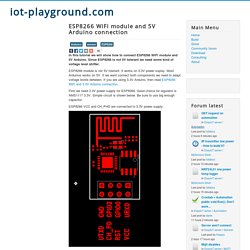
ESP8266 WiFi module and 5V Arduino connection. In this tutorial we will show how to connect ESP8266 WiFi module and 5V Arduino.

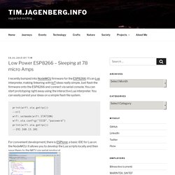
Since ESP8266 is not 5V tolerant we need some kind of voltage level shifter. ESP8266 module is not 5V tolerant. It works on 3.3V power suplay. Most Arduinos works on 5V. If we want connect both components we need to adapt voltage levels between. First we need 3.3V power supply for ESP8266. ESP8266 VCC and CH_PHD are connected to 3.3V power supply. AMS1117 3.3V power supply. Next we need shift voltage levels on data lines. Arduino TX -> ESP8266 RX Arduino DO pin -> ESP8266 reset To connect Arduino RX and ESP8266 TX you may try without level shifter. 3.3V should be enough for logical one in 5V Arduino. Low Power ESP8266 – Sleeping at 78 micro Amps. I recently bumped into NodeMCU firmware for the ESP8266.

It’s an Lua interpreter, making tinkering with IoT ideas really simple. Just flash the firmware onto the ESP8266 and connect via serial console. You can start prototyping right away using the interactive Lua interpreter. You can easily persist your ideas on a simple flash file system. print(wifi.sta.getip())--nil wifi.setmode(wifi.STATION) wifi.sta.config("SSID","password") print(wifi.sta.getip())--192.168.13.101 For convenient development, there is ESPlorer, a basic IDE for Lua on the NodeMCU. To make developing with the ESP-01 module easier, I created a basic development board. Although NodeMCU provides access to the deep-sleep mode of the ESP8266 node.dsleep(microSecs); this is not available straight away on the ESP-01 module, as the ‘post-sleep-reset-pin’ XPD_DCDC (8) of the MCU is not connected to the reset pin.
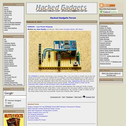
During deep sleep the module now uses just 78 microAmps! ESP8266 – Low Power Sleeping. The ESP8266 is quickly becoming a very popular chip, I am sure this is mostly due to the dirt cheap price point.

If you are adding this to a battery operated application you might want to drop the power consumption as low as possible. There are many things that can be done to do this, removing the indication LED is the first obvious step. Jagenberg.info has done some work in this area and has achieved some great results. 78 micro Amps is what can be expected with a flash of new firmware and a small hardware hack. “manually soldering a single wire of a stranded cable between the reset pin of the module and the XPD_DCDC (8) pin of the MCU, I also removed the red power LED by simply prying it off with a tiny screw driver.
With these two modifications, the module is able to make use of the deep-sleep mode and successfully resets and restarts after waking.” ESP8266 WiFi temperature and humidity sensor. The Best and the most popular esp8266 videos.
Nodemcu/nodemcu-firmware. ESP8266 Community Forum Index page.