

Oops! Google Chrome could not find www.atmel.com. Making an FM radio-Part 1; the TEA5767. I’ve started to build a little FM radio with one of this cheap modules with a Phillip chip, the TEA5767.
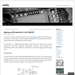
I will control it with a MSP430, probably I’ll use some kind of encoder to change stations and a potentiometer for the volume. The TEA5767 is a single-chip electronically tuned FM stereo radio for low-voltage applications with fully integrated Intermediate Frequency (IF) selectivity and demodulation. Most of the information of this devices is from the datasheet and this app note. Module Pinout The I2C-bus mode is selected when pin BUSMODE (PIN 3) is LOW. Some basic theory First of all let me explain some basics concepts about FM radio receivers in order to understand how to configure the different settings this chip has. The superheterodyne is a circuit arrangement that is the basis of almost all modern radio receivers. Structure of the Superheterodyne Receiver [c1] fLO= fd+fIF high-side injection fLO= fd-fIF low-side injection Don’t believe me?
Structure of a PLL. Programming ATMega16 without bootloader. Hi, I want to program this Development Baord with the Arduino IDE.The board has the following specs: AtMega16TEA5767 FM-Radio receiver chip (this is why i bought this board)10pin ISP connectorLCD1602 LCD connector4 pushbuttonsI do not want to use the Arduino bootloader because of the delay on powerup/reset.
I read through this article and took a look at the modified board.txt file from but they are all about using the bootloader and reference arduino 0020 or older. So here is my question: How do I have to modify the boards.txt and the pins_arduino.h file to make the IDE compile for ATMega16 and program with the USBTinyISP ? AVR USB FM Radio. AVR USB FM Radio (TEA5767,ATMEGA8) ---------------------说在前面的话------------------------------- 好久没发帖子了!
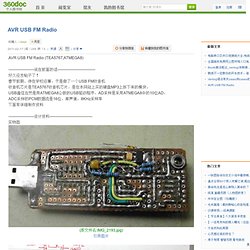
春节前期,待在学校没事,于是做了一个USB FM收音机 收音机芯片是TEA5767收音机芯片,是在本网站上买的硬盘MP3上拆下来的模块, USB通信当然是用ATMEGA8公版的USB驱动程序,AD采样是采用ATMEGA8中的10位AD, ADC采样的PCM数据流是16位,单声道,8KHz采样率 下面有详细制作资料 ---------------------设计资料----------------------------------- 实物图 (原文件名:IMG_2193.jpg) 引用图片. Tea5767 hot searching download - www.pudn.com. Atmega16做的数字收音机(液晶显示)_vigor. Atmega16做的数字收音机(液晶显示)_vigor. 我也上一个TEA5767做的调频收音机!M16+LCM1602(冷光屏)+TDA2822!全部资料! (amoBBS 阿莫电子论坛) Tea5767 hot searching download - www.pudn.com. FmTunerHardware. This page gives an overview of the various FM chips in current Rockbox targets and experimental Rockbox ports.
Philips/NXP TEA5700 family This family of FM tuners is the most popular in rockbox targets. Supported in rockbox by the tea5760uk.c driver. These chips are used in: Supported in rockbox by the tea5767.c driver. Sanyo LV24000 family General features: bus interface is a proprietary 3-wire protocol tuning requires a multi-step algorithm with assistance of the host microcontroller These chips are used in: Silicon Laboratories Si4700 family General features: few external components (basically an antenna and a crystal). Si4700/Si4702 These chips are basic FM tuners, without RDS support. Si4701/Si4703 These chips provide the same functionality as the Si4700/Si4702 but with RDS support added. RDA microelectronics RDA58xx family Quite similar to the Si4700 chips (even the same I2C address), but with a different register map. This chip is used in some Sansa Clip+ players. Samsung S1A0903X01. TEA5767 FM Radio Breakout Board for Arduino. Arduino FM receiver with TEA5767.
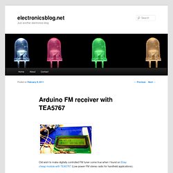
Old wish to make digitally controlled FM tuner come true when I found on Ebay cheap module with TEA5767 (Low-power FM stereo radio for handheld applications).
This module size is only 11.2mm x 11mm. TEA 5767 supports I2C. Pinout and wiring: TEA5767 FM Radio. I recently failed to resist buying two TEA5767 FM Radio modules from eBay for almost nothing.
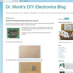
These little modules use the I2C serial protocol and so are ideal for connecting to an Arduino. These things are tiny. This image is much larger than the real thing. In fact, the connectors on the side are at a smaller pitch than the 0.1 inch found on the Arduino connectors. So, the first just was to make a little breakout connector using a bit of stripboard. First cut the tracks on the back like this: Then solder short lengths of solid core wire in place, either side of the breaks in the strips. Bend the cut ends inwards so that they will meet the connectors on the module. Before trying to solder the leads to the module, fit a crocodile clip over the leads to act as a heat sink, otherwise the leads are likely to become detached from the strips beneath. When all the pins are soldered, solder in a link wire between pins 3 and 6. I also attached 0.1inch header sockets for ease of experimentation.