
Starlight: Dimming a 12V LED strip with a mosfet and PWM. Dimming a 12V LED strip with an N-channel power mosfet is pretty straightforward.

In this experiment I'm using 5 meter of cool white LED strip running at about 800 mA giving 10 Watt. An Arduino Duemilanove (my trusty lucky white one) is used to provide pulse with modulation ( PWM ). Digital pin 9 and 10 (also known as OC1A and OC1B) are used. They both use the Timer2 facility of the atmega328p microcontroller which means I can have them output exactly the same PWM signal. Digital 9 is used to drive the mosfet and digital 10 is only used for displaying the unloaded PWM signal on the scope. The following Arduino sketch does a simple PWM sweep in 10 steps per second: 1 void setup() 2 { 3 pinMode( 9, OUTPUT); 4 pinMode(10, OUTPUT); 5 } 6 7 byte b = 0; 8 9 void loop() 10 { 11 analogWrite(9, b); 12 analogWrite(10, b); 13 delay(100); 14 ++b; 15 } This gives a PWM signal as shown in the (crude) video below.
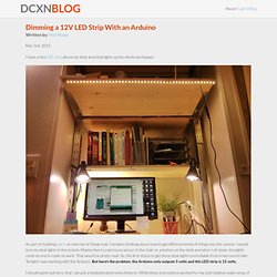
This is actually good enough for simple dimming, but lets look at it more in detail. Dimming a 12V LED Strip with an Arduino. I have a nice LED strip above my desk area that lights up the whole workspace: As part of building spirit, an internet of things hub, I’ve been thinking about how to get different kinds of things into the system.

I would love my desk lights in the system. Maybe there’s a pressure sensor in the chair or a button on the desk and when I sit down, the lights come on and is ready to work. That would be pretty neat. So, the first step is to get these desk lights controllable from a microcontroller. My DIY PWM LED dimmer. Maybe some pictures will get a little more interest?

I'm not trying to make any money at all, I'm sorry if I put anyone off in my initial post I just wanted to share this and see if anyone else could use it. The voltage range is actually between 0 and +V. This means that you can control the brightness in any manner you see fit -- I'm using a simple potentiometer, but you can use a photocell and resistor to make a light-sensitive voltage source. This would allow you to have the internal hood track the brightness of the sun outside, or by inverting it, have the internal hood maintain a constant light level in your tank despite other indoor lamps being on.
Here's a shot of its brightness (note, these LEDs have little to do with the controller I'm talking about, they are the leftovers from my lantern. Another brightness shot: The $13, 12v @ 3.5A power supply I'm using. The underside of the board, shown with a 20oz bottle for scale. Topside of the board: N-channel power MOSFET [30V / 60A] ID: 355 - $1.25. When you need to switch a lot of power, N channel MOSFETs are best for the job.
![N-channel power MOSFET [30V / 60A] ID: 355 - $1.25](http://cdn.pearltrees.com/s/pic/th/industries-electronics-55817457)
These FETs can switch over 60A and 30V and are TO-220 package so they fit nicely into any breadboard or perfboard. Heat sinking is easy with TO-220's, but because of the very low Rds(on) of down to 0.009 ohms (depending on the Vgs - check the datasheet) you can get away with no heatsinking for pretty high loads! The threshhold voltage is also very low, less than 2.5V so you can control it directly from a microcontroller running on 2.8V, 3.3V or 5V logic. RGB LED Strips. We love some good LED blinking as much as the next person but after years of LED-soldering we need something cooler to get us excited.

Sure there are RGB LEDs and those are fun too but what comes after that? Well, we have the answer: LED Strips! These are flexible circuit boards with full color LEDs soldered on. They take a lot of LED-wiring-drudgery out of decorating a room, car, bicycle, costume, etc. The ones we carry are also waterproof (although not all are). There are two basic kinds of LED strips, the "analog" kind and "digital" kind. The Digital-type strips work in a different way. You can buy waterproof analog-type RGB LED strips by the meter at the Adafruit shop! Choosing the right transistor for a switching circuit. Controlling high power (or high number of) LED’s with an Arduino. A while ago I posted about my bench lights, and have gotten a number of request for schematics and code.

I’ll gladly put the code up, but I also wanted to explain what I did so that others can create their own, or at least change my design up as they wish. The transistors I’m using are TIP122′s. You can find the data sheet here. They will switch a lot of power, but keep in mind, they need to have adequate cooling if you are going to push them hard. Always remember, fire = bad. I covered the basic schematic for a few LED’s in the video above, but if you have any questions, feel free to post them in the comments and I will answer as quickly as I can. You can download the original (controller with LCD and hard buttons) code here.
12V to 5V Converter.