

CMOS Synthesizers - Beavis Audio Research. Chip Basics For our experiments, we'll use a couple basic chips: 40106 Hex Inverting Schmitt Trigger: This chip contains 6 individual Schmitt triggers.

A Schmitt trigger is a comparator circuit that incorporates positive feedback. What this means is that when a high signal (positive voltage defined as '1') is applied to the input pin, the output pin generates a low signal (ground voltage defined as '0). This simple circuit can be connected to a resistor/capacitor pair to rapidly turn on an off. 4040 Binary Counter/Divider: This simple logic chip takes an input square wave and generates oscillations at 8 outputs with a frequency related to the input frequency. 4051 Eight Channel Analog Multiplexor/Demultiplexor: The voltage status of the three address pins A, B and C determines which of the eight channels presents its voltage to the common connection pin.
Home page. Intro to Lunetta CMOS Synths. LOS APARATOS: Suboscilador a paso de hormiga. La muerte térmica se aproxima amigos, agitemos esos electrones mientras se pueda.
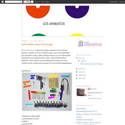
Acá otro instructivo paso a paso, bien detalladito para que todos y todas y tados podamos tener en casa un suboscilador, alimentarlo con su pilita de nueve voltios, darle de beber ritmos tropicales o fríos como la cajeta de Margareth Tatcher y de vez en cuando sacarlo a pasear para presumir con sus lucecillas parpadeantes. Electronoize Playshop: 4093 Oscillator. Last week we built our first oscillators, based on the 40106 chip.
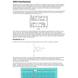
Hopefully you were able to get several oscillators working, mixed some of the outputs together, and maybe even connected 2 oscillators together (using the diode) so that one oscillator controls (or “modulates”) the other. That basic building block allows hundreds of variants--stringing them together in different ways, mixing, and various ways of controlling--so don’t shortchange the possibilities of just that one chip, and keep playing.
This week we’ll introduce a very similar oscillator using a different chip, which will allow you to connect them together in a slightly different way. (BTW, this again is straight out of the Nic Collins book, which I will recommend again.) The new chip is the 4093 quad NAND gate, and here’s its pin-out: First, notice the circuit elements: 4 identical NAND gates, which implement a particular logic rule… which you could look up if you care. Oscillators 1, 2… One oscillator after the other. 4093 Quad Oscillator Kit. The GetLoFi Quad Oscillator Kit is based on the 4093 Logic IC configured to create four independent oscillators controlled by knobs.
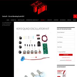
The resulting sound can vary from rhythmic beeping to polyphonic drones. Price: $35 Please order the Quad Oscillator Kit from the www.getlofi.com/shop Demo: From the GetLoFi.com/shop you can also purchase an acrylic panel that is laser cut and fits perfectly inside of a Radio Shack Medium box enclosure. If you have a some sheet metal or an Hammond type enclosure then you should be able to use this Drill template to make all of the potentiometer controls line up. ElectroNoize Playshop: 386 Amplifier. This project is based on the Little Gem amp ( It’s a 1/2-watt amplifier similar to a bunch of tiny practice guitar amps; it uses a single integrated circuit and just a handful of components.
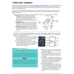
The version we’ll build has a single “gain” control; this is like the drive control on a guitar amp, turning it up will give a “dirtier”, more distorted sound. We’ll use this as an introduction to building circuits on a breadboard, as well as introducing a couple new kinds of components and schematic symbols. We’ll also be using this amp to listen to the oscillators and stuff we’ll start building next session. That’s basically it. Test it out: Connect a contact mike/piezo element (little brass disk) to the input: red wire to the “In” connection on the .01uf cap; black wire to ground. Coolness. If nothing’s hot and it’s still not working just start tracing your connections one at a time; I usually start with the power connection, then ground, then with the input and work my way from left to right.
Gijs's Personal Home-Page « Gieskes.nl. Music From Outer Space - Your Synth-DIY Headquarters. Audio - Do-It-Yourself Circuits. DIY-page Welcome to the Gyraf Audio DIY-page.....
Please read this first!! The projects described on these pages are not commercial in any way. This means that we DO NOT sell PCB's, kits, or anything like that. It also means that any for-profit use of the information on these pages is strictly prohibited. Please DO NOT contact us regarding parts or info for the DIY-projects, as we don't sell anything related to these - they're kept strictly non-commercial. 20. Here's the link to the Prodigry-pro forums (AKA GroupDIY) - our meeting place and hangout for all things audio, electronic and DIY. Gyraf Do-It-Yourself Circuits This pages contain information about building your own professional audio equipment. Comments and corrections are more than welcome, but I can't promise to reply to all mail. Disclaimer: Notice that all information, schematics, layouts etc. are supplied "as is", and that we can in no way be held responsible for its acurateness, functionality or even safety. Befaco. Familiar.