

RF decibel meter circuit ~ electronictheory. Return Loss Bridge for the Radio Amateur. A return loss bridge is a wideband resistive bridge network which can be used to verify the impedance of coaxial cables, antennas, tuning stubs, filters, etc.
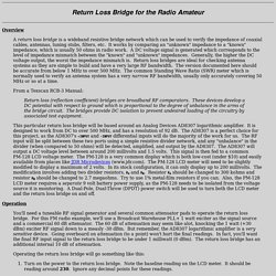
It works by comparing an "unknown" impedance to a "known" impedance, which is usually 50 ohms in radio work. A DC voltage signal is generated which corresponds to the level of impedance mismatch between the "known" and "unknown" impedances. Generally, the higher the DC voltage output, the worst the impedance mismatch is. Return loss bridges are ideal for checking antenna systems as they are simple to build and have a very large RF bandwidth. 30W Digital RF Wattmeter.
Background This watt meter project is very similar to my last wattmeter project.
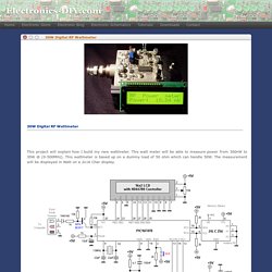
The main reason I made a new project is becasue I needed a unit which could handle higher power than 1W. n2pk_ad8307_power_meter.pdf. Instrument Electronic. Nordic nRF24L01+ Example Code. As can be seen, it uses a PCB antenna.
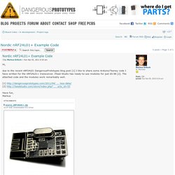
No need for an external one. The maximum distance is greater when using 250 kbps compared to 1 Mbps. The range depends on the "things" between the two Nordic devices. nRF24L01 Wireless Module with Arduino. Now we have a demo show how to use the Arduino controlling the nRF24L01 module , and you need two Arduino boards and two modules, one to transmit and the other receive.
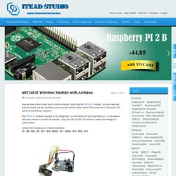
The connection of two part is the same but the different software. The nRF24L01 module is worked at 3V voltage level , so the Arduino 5V pins may destroy it , so we need to add some resister to protect the module – using the 10K and the 15K resister to reduce the voltage is a usual method. Connect the module pins to Arduino as below: Download the code below into the TX Arduino (transmit) — This code will drive the nRF24L01 module to send out data form 0×00 to 0xFF . Download the code below into the RX Arduino (receive) – This code will drive the nFR24L01 module to receive the data that transmit form the TX module and print it to serial port.
2.4G Wireless nRF24L01+ Module 2.4G Wireless nRF24L01 Module [WIR001] - $5.50 : iStore, Make Innovation Easier. This module uses the newest 2.4GHz transceiver from Nordic Semiconductor, the nRF24L01+.This transceiver IC operates in the 2.4GHz band and has many new features!
![2.4G Wireless nRF24L01+ Module 2.4G Wireless nRF24L01 Module [WIR001] - $5.50 : iStore, Make Innovation Easier](http://cdn.pearltrees.com/s/pic/th/wireless-nrf24l01-innovation-105099839)
Take all the coolness of the nRF2401+ and add some extra pipelines, buffers, and an auto-retransmit feature. Now we make a breakout for nRF24L01+ , and build the smallest system for it , also the wireless circuit . KAUNE. TF3CY – Benedikt Sveinsson. Building a amplifier like this ground up is quite a task, and requires a lot of commitment .
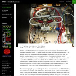
This started by me needing approx. 1 KW of RF power on 144Mhz for EME use. I originally built a 2M amplifier using a 4cx1000K tube. The tube failed and I had to spend $500 for a new tube. Premium Quality Electronic Kits, LC Meter Kit, 60MHz Counter Kit, XR2206 Function Generator Kit, Transmitter Kits, Volt Ampere Meter, RF Remote Control, Electronic Components, BA1404, BH1415, BH1417, TDA7000, 38KHz Crystal, 7.6MHz Cr. 60MHz Frequency Meter / Counter kit measures frequency from 10Hz to 60MHz with 10Hz resolution.
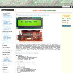
It is extremely useful bench test equipment for testing and measuring frequency of oscillators, transmitters, radio receivers, function generators, crystals, etc. Counter provides exceptionally stable readings and has excellent input sensitivity thanks to onboard amplifier and TTL converter. 0-500MHz RF Power Meter Probe Kit - Electronics-DIY.com. Electronics-DIY.com - Premium Quality Electronic Kits, LC Meter Kit, 60MHz Counter Kit, XR2206 Function Generator Kit, Transmitter Kits, Volt Ampere Meter, RF Remote Control, Electronic Components, BA1404, BH1415, BH1417, TDA7000, 38KHz Crystal, 7.6MHz Cr. With Accurate USB 0-500MHz RF Power Meter measurement of transmitter's output RF power has never been easier and more precise.
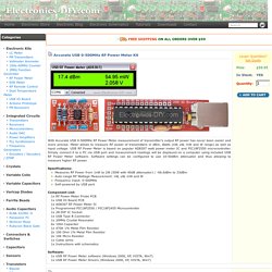
Meter allows to measure RF power of transmitters in dBm, Watts (nW, uW, mW and W range) as well as input voltage. USB RF Power Meter is based on popular AD8307 watt power meter IC and PIC18F2550 microcontroller. Simply connect it to a PC via USB port and measurement readings will be displayed on a computer using included USB RF Power Meter software. Software settings can be configured to use 10-50dBm attenuator and thus allowing to measure higher RF power. Specifications: Introduction - Sound Card Packet. RF testing calibration is critical. Logarithmic Amplifier with AD8307 from Analog Devices. Categories Statistics Since 08.08.2014.
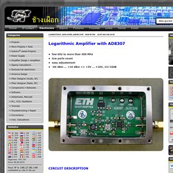
A very simple to build, menu driven RF Power Meter, based on the AD8307 log amp - Loftur E. Jónasson - TF3LJ / VE2LJX. Back to main page (Page last updated 2014-02-13.
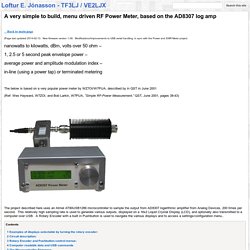
New firmware version 1.08. Digital Wattmeter with AD8307, PIC16F876, LCD Display. Digital Wattmeter English mainpage Vis Dansk oversat side NEW SOFTWARE AVAILABLE 28 okt 2008 The input board is a small PCB mounted directly on the connector. The main CPU board is mounted directly on the display. ARDUINO PROJECTS. This sketch will readout RF power and SWR from any SWR bridge (for example 'monimatch' type). As this 'monimatch' type of bridge is frequency dependant, the meter must be calibrated for every band. HF_bridge_diode_FWDvoltage_compensated.pdf. OH2NLT_bridge.pdf. SWR Bridge. Building Instructions: 1. Inventory all Parts 2. Install all Resistors. Note: Bend the resistor leads a sharp 90 degrees from the body. Homebrew swr meter. K6JCA: More Notes on Directional Couplers for HF.
In a previous post I looked at how the popular "Tandem-Match" Directional Coupler worked. Recall from that analysis:I analyzed the Tandem-Match coupler in terms of "lumped" circuit elements, not distributed elements.The coupler works by taking a sample of the voltage across the transmission line at a single point and a sample of the current through that point. The Tandem-Match Coupler creates both of these samples with transformers.The voltage at the "Forward Port" (that we measure on our meter) is calculated by adding the current and voltage samples.The voltage at the "Reflected Port" is calculated by subtracting the current and voltage samples.The voltage at the "Reflected Port" is 0 when the load is a real resistance equal to the value of the resistors terminating the measurement ports (Forward and Reflected Ports). I'll analyze the original design as well as some of the variants it inspired.
So here we go! 302C-3%20%283rd%20ed-%2001-15-60%29.pdf. ALL THINGS RADIO @ NØFP. Rolling your own furnace controller. [Viktor’s] found an opportunity to put his embedded design skills to use when the furnace controller in his building went out. Computer monitor Ambilight clone shows remarkable performance. Checking Email With The ESP8266. Ever so slowly, everyone’s favorite WiFi adapter is making its way into Internet-enabled projects. Watt Meter build walks you through Power Measurement basics. Ambilight clone uses video pass-through; needs no computer. Weather monitoring. PIC based USB input devices. PIC USB host shortcuts. Debounce Code – one post to rule them all. Cheap and easy logic signal generator.
Arduino PIC programmer writes to 18F family. PIC 18F4550 dev board. USBPIC controls just about anything. Fubarino Contest: Serial Data Transmission. Kernel driver for the PIC18F4550 microcontroller. Arduino IDE Support for the ESP8266. Once Around the Block. Temperature Sensing. Steinhart–Hart equation. Thermostat with LCD Screen - Tufts Robotics Club. Sensors by Measurement Specialties. HAM radio software - Programs for amateur radio. Test Equipment / Technical Reference: Test Equipment. Universal Active Filters: Part 1. Hacklet 31 – Software Tools. Get Serious with Amateur Radio; Design & Build a Single-Sideband Transceiver from Scratch Part 1. Design & Build Part 2: Multi-Band, Phasing SSB, and SDR. Logic Noise: Sawing Away with Analog Waveforms. [Afrotech]’s Guide To Class D Amplifiers. Instrumentation Amplifiers and How to Measure Miniscule Change. Filtering out mains hum from ADC samples.
Mooshim Engineering. Making a Variable RF Signal Sampler. Variable RF Signal Sampler. An ESP8266 Based Smartmeter. Hackaday Prize Finalist: An Un-noodly Spectrometer. RTL SDR As A Spectrum Analyzer. Direct Digital Synthesis (DDS) Explained by [Bil Herd] Easy and Effective Way to Measure PWM… Without a Scope! Scope Noob: Probing Alternating Current.
Scope Noob: Microcontroller Quirks with DDS. Faulty ESP8266s Release Smoke, Then Keep Working? Solar Panel System Monitoring Device Using Arduino. Measuring tiny current with high resolution. Measuring Frequency Response with an RTL-SDR Dongle and a Diode. Fail Of The Week : Measuring DC Current Has To Be Easy, Right? Measuring Filters and VSWR With RTL-SDR. Maker Stuff. YAT. Logic Analyser. Project & Electronics. ESP8266. Watch these video's. Nodemcu/nodemcu-firmware. Getting Started With The ESP8266 WIFI Microcontroller. ESP8266 Community Forum View topic - Has anyone PULLDOWN on GPIO-pins working? First Steps with the ESP8266-03 Development Board - Limpkin's blog. How to Directly Program an Inexpensive ESP8266 WiFi Module. Excel Unusual.
Scargill's Tech Blog. Community Forum View topic - My Espressif DevKit for Windows + Eclipse IDE. ESP8266 - NURDspace. ESP8266 weather display. PlanetArduino.