
Tutoriel Arduino : asservissement en vitesse d’un moteur à courant continu. Introduction L’asservissement en vitesse d’un moteur à courant continu est la plupart du temps nécessaire pour les robots mobiles.
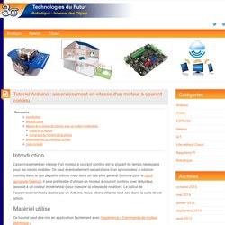
On peut éventuellement se satisfaire d’un servomoteur à rotation continu dans le cas de petits robots mais dans un cas plus général (comme pour le robot gyropode Geeros), il sera préférable d’utiliser un moteur à courant continu avec réducteur, associé à un codeur incrémental (pour mesurer la vitesse de rotation). Le calcul de l’asservissement sera réalisé par un Arduino. Nous allons détailler tout ceci dans la suite de cet article. Matériel utilisé Ce tutoriel peut être mis en application facilement avec l’expérience « Commande de moteur électrique ». La carte Romeo est intéressante car elle intègre de façon très compacte le micro-contrôleur (AVR Atmega328, le même cœur qu’un Arduino Uno) et un double pont en H permettant de contrôler deux moteurs à courant continu avec un courant max de 2 A en permanence (jusqu’à 3 A en pic).
Calcul de la vitesse Code complet. Motor Control using PWM and PID. Bi-directional motor control can be done using an H-bridge circuit with pulse-width modulation (PWM) from a microcontroller to vary the speed.
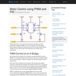
Several design challenges include preventing shoot-through, implementing a snubber circuit, as well as open and closed loop (such as PID) control mechanisms. An H-bridge circuit consists of four transistors (usually two PMOS’s and two NMOS’s). To maximize efficiency, the transistors are driven at a higher voltage than the microcontroller. A typical H-bridge circuit with logic scaling circuitry is shown above. Each side of the H-bridge has two transistors with the gates tied together resulting in complementary operation–Q3 is always off when Q1 is on and vice versa.
PWM is a simple way to vary the voltage applied to the motor. While using PWM is simple, it introduces a problem called shoot-through which occurs when current flows directly from the power supply to ground when the transistors are being switched. Preventing Shoot-through PID Control. Arduino robot kit – Wiring Diagram ← Ad Hoc Node. I have created this wiring diagram for the connections between the motor controller, motors, and sensor shield.
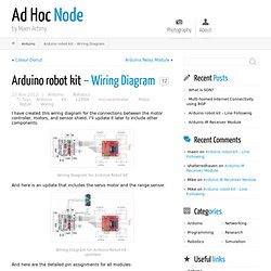
I’ll update it later to include other components. Wiring Diagram for Arduino Robot kit And here is an update that includes the servo motor and the range sensor. Wiring Diagram for Arduino Robot kit – updated And here are the detailed pin assignments for all modules: Disclaimer: The diagrams above are not the only way you can connect the components so use at your own risk. FunnyRobotics: Arduino With L298N Based Dual Motor Controller.
The ControllerA motor controller is a device that serves to govern in some predetermined manner the performance of an electric motor.
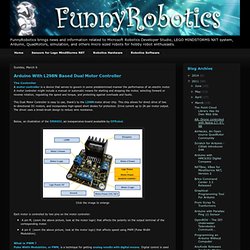
A motor controller might include a manual or automatic means for starting and stopping the motor, selecting forward or reverse rotation, regulating the speed and torque, and protecting against overloads and faults. This Dual Motor Controller is easy to use, thank's to the L298N motor driver chip. This chip allows for direct drive of two bi-directional DC motors, and incorporates high-speed short diodes for protection. Drive current up to 2A per motor output. The driver uses a broad-brush design to reduce wire resistance.Below, an illustration of the DRI0002, an inexpensive board avalaible by DFRobot. Click the image to enlarge Each motor is controlled by two pins on the motor controller: A pin M, (zoom the above picture, look at the motor logic) that affects the polarity on the output terminal of the corresponding motor.
Click the image to enlarge.