Xoscillo - A software oscilloscope that acquires data using an arduino or a parallax (more platforms to come).
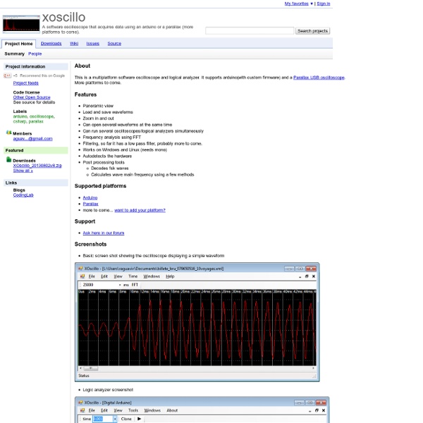
About This is a multiplatform software oscilloscope and logical analyzer. It supports arduino(with custom firmware) and a Parallax USB oscilloscope. More platforms to come. Features Panoramic view Load and save waveforms Zoom in and out Can open several waveforms at the same time Can run several oscilloscopes/logical analyzers simultaneously Frequency analysis using FFT Filtering, so far it has a low pass filter, probably more to come. Supported platforms Support Ask here in our forum Screenshots Basic screen shot showing the oscilloscope displaying a simple waveform Logic analyzer screenshot Displays the FFT of the signal and underneath the FFT over time. This screen shot shows an arduino based oscilloscope and a parallax one working simultaneously in realtime. Linux Notes from the Author The code is not by any means great, its just a quick exercise I did to learn c#. License
Arduino Chicken Coop Controller
Over the last few years my family has been keeping ex-battery hens - they are about 18 months old and have had a horrendous life kept cooped up in small cages in large warehouses. As much as we love these little bundles of joys and eggs it can be a drudge getting up in the early morning letting them out to roam the garden because the sun is up and bright at 5.00am!! It would be great if we could have an automated door that could open just after sun rise and close half an hour after sunset where hopefully they are all cosying up to each other in the coop. Sadly there have been times we have forgotten to lock them safely away and discover the horrible consequences when a fox has attacked and killed some of them. The main features of the ACCC:
DIY intervalometer based on Arduino « Rastroludico
I would like to share with you my Intervallino project with all the steps and details it involved. When I started looking for similar projects on the web I found extremely useful to have a look at either the circuit schematics or snippets of code or even soldering videos! For this reason I try here to be the most complete and precise that I can, so to give some hints and ideas to anyone willing to make a similar project. That said, I assume one has some basic electronics knowledge and is not too afraid of writing a program… Indeed, this is not a manual on electronics nor an arduino programming tutorial but, as the title says, just a detailed “making of” ;) I have seen many beautiful time-lapse photography in the last times (e.g. I thought a do-it-yourself (DIY) intervalometer would perfectly fit as my first electronic project since it would merge many things I like – photography, electronics and programming – into a compact, portable, box! where the remote looks like this: The brain Tools
The Laser Doodler | ch00ftech Industries
So I've got a project coming up (that may have something to do with this tweet) that will require a few LED matrix displays. I found a suitable candidate online and ordered one to play around with. Since I already had the display, I thought it'd be fun to run it through the paces and build a little circuit out of it using some parts I had lying around. What I came up with is the "Laser Doodler." So when this display arrived in the mail, I wanted something to do with it so I could get accustomed to the pinout and LED intensity. I thought it would be fun to create a simple display that can be "drawn on" with a light source. In order to accomplish this, the display needed to alternate between being a display and being a sensor. A while back, I wrote an article about using LEDs as light sensors. That demonstration was an incredibly quick and dirty hack, and it only worked for a single LED. The display is a BL-M12A883DUG-11 which I found on Adafruit for $7. So that's the easy part.
Related:
Related:


