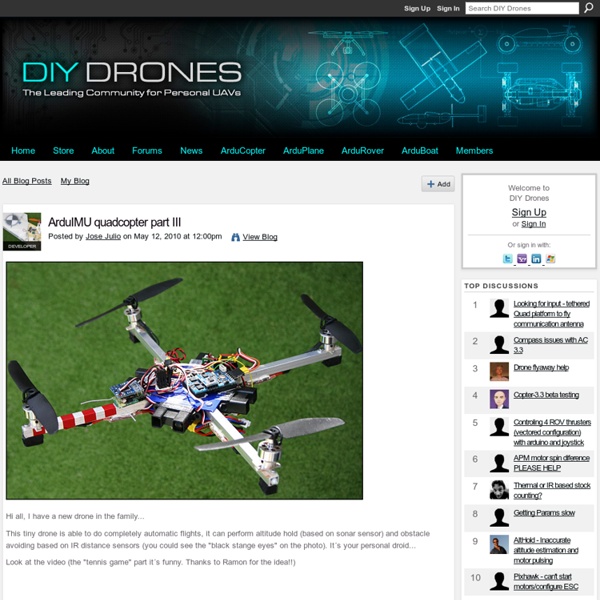
ArduIMU quadcopter part III

The DIY Kid-tracking Drone
On school-day mornings, I walk my grade-school-age son 400 meters down the hill to the bus stop. Last winter, I fantasized about sitting at my computer while a camera-equipped drone followed him overhead. So this year, I set out to build one. On the mechanical side, there’s a central frame to hold the electronics, spars of aluminum to support the motors and propellers, and legs to cushion the quadcopter’s landing (I made a few extra sets of legs out of foam board for easy replacement). On the electronics side, there’s a main control board plus sensors, batteries, a power distribution board, power controllers for the motors (which draw tens of amperes, not what you’d manipulate with ordinary microcircuitry) and a radio receiver for standard remote-control flying, plus an RF modem for computerized control—I got both control systems for redundancy. Getting the quadcopter built and into the air was almost too easy. So, did it work?
Document sans nom-Mozilla Firefox
Accueil Pour votre premier robot (le MINIBOT) nous avions utilisé deux servo moteurs pour la propulsion ce qui est la solution la plus simple. Mais si vous voulez par la suite évoluer vers des robots plus lourds (au dela de 1 Kg) il faudra utiliser des moteurs a courant continu . Pour aborder cet autre type de propulsion nous avons choisi a nouveau un petit robot (MINIBOT-DC , pour Direct Courant) en nous inspirant des plans d'un robot décrit par des Enseignents de Polytechnique Montréal (merci a eux pour leur exposé trés pédagogique et détaillé ). Chassis du robot Le chassis du robot est un rectangle d'environ (14 sur 20 cm) dont on coupe les 4 coins sur environ 2 cm pour limiter les rique d'accrochages lors des déplacements du robot. Ce chassis est découpé dans une plaque de "verre synthétique" de 3mm d'épaisseur qu'on trouve dans le magasins de bricolage (Bricorama pour nous).Ces plaques n'éclatent pas lors du percage ou du découpage a la scie a métaux. Montage des Moteurs et pont H Init
Help choosing my first DIY quadrocopter for up to 600usd : diydrones
Related:
Related:


