Raspberry Pi | Wiring
Update: 14th May, 2013 wiringPi version 2 has been released and now has its own website ( to look after it. Most of the documentation on the projects site has been copied over to it the new site, but there may still be 1 or 2 pages that are still missing. I’d encourage you to use the new site if possible where there will be a forum and wiki (when I get time to implement them!) WiringPi is an Arduino wiring-like library written in C and released under the GNU LGPLv3 license which is usable from C and C++ and many other languages with suitable wrappers (See below) You may be familiar with the Arduino… Briefly; Arduino is really two things; one is a hardware platform, the other software, and part of the software is a package called Wiring. The Raspberry Pi has a 26-pin General Purpose Input/Output (GPIO) connector and this carries a set of signals and buses. WiringPi includes a command-line utility gpio which can be used to program and setup the GPIO pins. Pin numbering
Pins | Wiring Pi
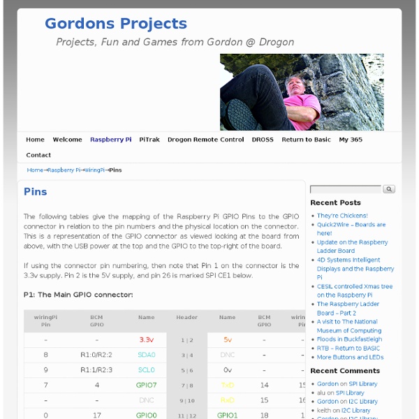
Pin numbering of the BCM2835 GPIO port(s) on the Raspberry Pi has been a source of great confusion since the designs for the Pi were first published. In the early days (even before hardware was available) the default usable GPIO pins were simply referred to by number as GPIO0 through GPIO7. Additionally there were pins for other purposes, SPI, I2C and serial. This was highlighted on the original image on the Raspberry Pi Wiki site too. So when initially writing wiringPi, I chose to have the same default pin numbering scheme and numbered them from 0 upwards. However this has subsequently been viewed as “wrong” and several people have expressed concern about my numbering scheme, however I’ve stuck with it (as by then people were using wiringPi). and it’s proven its worth over the hardware board revisions where some pins changed their hardware definitions, however wiringPi was able to hide this from the user. For a printable version of these tables, click here.
RPi Low-level peripherals
Back to the Hub. Hardware & Peripherals: Hardware and Hardware History. Low-level Peripherals and Expansion Boards. Screens, Cases and Other Peripherals. Introduction In addition to the familiar USB, Ethernet and HDMI ports, the Raspberry Pi offers the ability to connect directly to a variety of electronic devices. Digital outputs: turn lights, motors, or other devices on or off Digital inputs: read an on or off state from a button, switch, or other sensor Communication with chips or modules using low-level protocols: SPI, I²C, or serial UART Connections are made using GPIO ("General Purpose Input/Output") pins. Note that no analogue input or output is available. Links For further specific information about the Raspberry Pi's BCM2835 GPIOs, see: RPi BCM2835 GPIOs. Model A and B (Original) The Raspberry Pi Model A and B boards have a 26-pin 2.54 mm (100 mil)[1] expansion header, marked as P1, arranged in a 2x13 strip. Revision 1 PCBs also do not have the P5 header (see below). Useful P2 pins:
The GPIO Connector | Adafruit's Raspberry Pi Lesson 4. GPIO Setup
The diagram below show the pins on the GPIO connector for a Raspberry Pi Version 1 (which is what existed when this tutorial was released) Version 2 has pin 27 replacing pin 21 but it otherwise the same As well as supplying power (GND, 3.3V and 5V) all the GPIO pins can be used as either digital inputs or outputs. The pins labelled SCL and SDA can be used for I2C. The pins labelled MOSI, MISO and SCKL can be used to connect to high speed SPI devices. All the pins have 3.3V logic levels and are not 5V-safe so the output levels are 0-3.3V and the inputs should not be higher than 3.3V. A popular way to actually make the connections to the Raspberry Pi is to use a Pi Cobbler. Make extra extra double-check sure that the PIN 1 indicator is in the corner of the Pi. This uses a ribbon cable to connect the GPIO connector to solderless breadboard, where you can add your own components.
algorithm - How to detect BPM of the song by programming
DomoRasPi
Beat Detection Algorithms
This document is to be distributed for free and without any modification from its original state. The author declines all responsibility in the damage this document or any of the things you will do with it might do to anyone or to anything. This document and any of its contents is not copyrighted and is free of all rights, you may thus use it, modify it or destroy it without breaking any international law. However according to the author's will, you may not use this document for commercial profit directly, but you may use indirectly its intellectual contents; in which case I would be pleased to receive a mail of notice or even thanks. Simulating a physical phenomena which obeys to known mathematical equations is, with a number of approximations, always feasable. 1 – Simple sound energy a - A first analysis The human listening system determines the rhythm of music by detecting a pseudo – periodical succession of beats. Simple sound energy algorithm #1: Every 1024 samples:
Wiimote
This article will go through the basic steps required to have a working Wiimote in Linux for general use. It will not go into much detail for some steps as there are many guides already written for some parts already. Note: The approach shown on this page is based on software which is no longer developed upstream. Prerequisites Bluetooth cwiid Wiimote The most important piece required is Bluetooth, this must already be configured and running without the help of this guide. Connect the Wiimote First you need to make sure to load the uinput module: $ sudo modprobe uinput You should have a device in /dev/uinput now. Thanks to cwiid you can scan for your Wiimote now: (press the 1 and 2 buttons on your Wiimote) $ hcitool scan Scanning ... Once your Wiimote has been detected you can test if it is working by running the command wmgui and testing out various buttons and sensors through that interface. Input Device The Wiimote can act as a regular input device like a mouse using wminput. $ wminput -w