background preloader

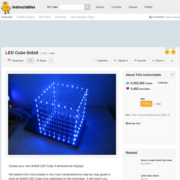
Led Cube 8x8x8

Led Cube 8x8x8
A wireframe box is a good geometric shape to show in a monochrome 8x8x8 LED cube. It gives a very nice 3d effect. We made two box animation functions for the LED cube. Effect_box_shrink_grow() draws a wireframe box filling the entire cube, then shrinks it down to one voxel in one of 8 corners. Here is how effect_box_shrink_grow() works. It takes four arguments, number of iterations, rotation, flip and delay. To make the function as simple as possible, it just draws a box from 0,0,0 to any point along the diagonal between 0,0,0 and 7,7,7 then uses axis mirror functions from draw.c to rotate it. 1) Enter main iteration loop. 2) Enter a for() loop going from 0 to 15. 3) Set xyz to 7-i. 4) When i = 7, the box has shrunk to a 1x1x1 box, and we can't shrink it any more. 5) Blank the cube and delay a little bit to make sure the blanking is rendered on the cube. 6) Draw the wireframe box in its original rotation. side of the box is always at 0,0,0 while the other travels along the diagonal.

LED Flower – Wiki Chaostreff Göttingen Aus Wiki CCC Göttingen LED Flowers are a set of PWM-controlled RGB LEDs which get their settings via USB using obdev.at's USB stack. Everything needed for this workshop is under a free license, so feel free to copy and modify. To get started, you first need all the parts and a PCB. Sources Sources are available here: Circuit Diagram Necessary Version 1: USB Powered Version 2: Externally powered Option: Button Tutorial Preface This Tutorial consists of three parts. If you don't want so modify the project to look like something else (which of course would be perfectly okay) make sure that you execute every step exactly as described. If you encounter any problems with your device, you may also ask Marvin for support, but only if you include a correctly focused photograph of the bottom of your PCB that has an adequate resolution and an exact description of your problem. Prerequisites Clean the board with aceton before soldering. Part I: The PCB Microcontroller

Творим оригинальный подарок при помощи химии физики и электроники / DIY или Сделай Сам Добрый день, уважаемые хабровчане. Так получилось, что я уже довольно долго занимаюсь разработкой электронных устройств на базе микроконтроллеров, микропроцессоров и ПЛИС. Одним из разработанных мной девайсов я хочу с вами поделиться. Идея Идея пришла ко мне во время просмотра статей на Википедии, а именно статьи про сульфат меди (медный купорос), в которой есть картинка кристалла, выращенного в домашних условиях. В процессе обдумывания я пришел к следующему девайсу: выращенный кристалл сульфата меди должен быть помещен в прозрачный стеклянный цилиндр вместе со светодиодом для подсветки и небольшой электронной схемой, которая управляет светодиодом. В результате реализации получилось следующее: На видео показан сам кристалл, собранный девайс, и девайс с уже подключенным питанием и прошитим кодом. Теперь я постараюсь кратко изложить процесс создания такого устройства. Шаг 1: выращиваем кристалл Из школьного курса физики мы помним, что растить кристаллы солей из водных растворов нетрудно.

LED Pong Clock « LED Projects Version 5.1 of the firmware is out. It contains bug fixes and some sweet lower case font action. NOTE: If you upgrade, please replace all 4 libraries as well as the main code. BTW, if anyone fancies designing a case for this let me know! This clock uses the classic video game Pong to tell the time. Pong ClockLarge DigitsTime written in words, e.g. The project uses 2 bright LED matrix panels from Sure Electronics. 2 x Sure Electronics 2416 LED Matrix (24×16 pixels) in Red or Green (Make sure you get the version based on the HT1632C and not the HT1632 – more detail below).1 x Arduino Duemilanove / Uno with ATmega 328 CPU1 x DS1307 real time clock chip and IC socket1 x Crystal oscillator for the DS13071 x 3.3v coin cell battery and battery holder for the DS13071 x Arduino prototyping shield1 x Breadboard and jumper wire for testing or if you don’t want to solder (optional)1 x 16 Pin IDC Socket for the display connection2 x Push to make buttons1 x USB Lead1 x Mains to USB power adapter Power

Цветная светодиодная лампа своими руками / DIY или Сделай Сам Световой день уменьшается, поэтому жена всё чаще стала вспоминать о подсветке для орхидей. Поскольку в светодиодной тематике я уже довольно давно, то решил: «почему бы и нет». В качестве лампочек, это моя первая лампа, раньше я делал только велофары. Почитал какой свет народ рекомендует, решил, что по большому счёту, нужен весь спектр, но больше красного и следом за ним синего. Заказал светодиоды: два красных, один янтарный, два холодных белых с зелёным оттенком. Когда все материалы были в сборе, не мешкая приступил к постройке лампы. Итак, лампа-донор была сразу без абажура: Отворачиваю патрон: Крепление очень удобное для дальнейших целей. Отрезаю кусок профиля: Внутренний диаметр трубы 54 мм, пока я гулял с ребёнком, в уме высчитал, что при стороне 29.5 мм вторая сторона прямоугольника будет 44 мм. На домашней настольной циркулярке сделал канавки, чтобы улучшить охлаждение: Охлаждение светодиодов — самая главная проблема. Вот так вертикально будет стоять радиатор: Итоговый результат:

LED Fade-In Fade-Out Dimmer - Electronic Theory The second question is general about maximmum current I can pass through BD243. It is aroud 5A at 13V. You're doing a lot of enlightenment, thanks. I want to leave fade-out. I want to make it simplier. In circuit #2 I want to remove S1, Q2, R5, R6 and connect R4 to 0V negative. (i was rejected from forum) Note: I also tried the power transistor BD243 and I get the exact same brightness and the exact same voltage out ( 8.25V out ) Thanks Dan Thanks! I need this circuit in a quite different way to use it as an effect controller by an ldr, I want to control 3 variables independant - set the minimum light intensity (0 to 100%) - set ramp time to 100% intensity by a pot - set ramp time to 0% intensity (overruled by minimum setting) I simulated this simple circuit on my computer but i can't get it done Is there anybody who can help me out? Thanks in advance sorry but only now I realise that I have a AC voltage so I have to think about the zero crossing and the modulation of the wave ;) andrea Thanks.

Любительская голография Любительская голография — голографические технологии, использующие непрофессиональное оборудование. Схема Денисюка Схема Денисюка при применении лазерного диода в качестве источника когерентного света оказывается предельно простой, что позволяет записывать такие голограммы в домашних условиях без использования специального оборудования. Для записи голограммы достаточно создать некий каркас, на котором будут неподвижно установлены лазер, фотопластинка (как правило, ПФГ-03М) и объект записи. Лазеры, используемые в любительской голографии В любительской голографии используются дешёвые и доступные полупроводниковые лазеры: лазерные указкилазерные модулиотдельные лазерные диоды Лазерные указки являются самым простым в использовании и доступным источником когерентного света. Более совершенным источником является лазерный модуль, у которого опять таки нужно выкрутить или отпилить фокусирующую линзу. Наконец, лазерные отдельные диоды являются самыми сложными в эксплуатации источниками света.

The Making of Phill's Pet When I saw Phil’s Pet on Flickr (on the left. Click for a bigger view) I knew I just had to learn how it was taken. Gladly for us, Trevor agreed to share the setup and production process of this wonderful light painting. It came as no surprise that this photograph is a very integrative effort. Integrative in the sense that it takes lots of techniques and puts them into one creative vision. P.S. no birds were harmed during the production. I had an idea for a light painting shot that would have a model holding a cage of light with our trademark character Fiz-bird inside. The Gear You Will Need: A camera with manual mode and that is capable of long exposuresA cable releaseA tripodSpeedlites x 2 (remote triggers were used here but are not necessary)Stencil boxLight hoop To build a hoop you will need: Building a Light Hoop – Fixing the LED strings Use battery powered LED decoration lights. If you attach them as is you will have 6 switches to turn on which is not ideal. Building a Light Stencil Box

Любительская голография - Наука и технология Хочу рассказать о необычном хобби - изготовлении голограмм в домашних условиях. Голограмма - это изображение предмета, хранящее информацию не только о интенсивности световой волны, но и о ее фазе. С точки зрения зрителя это выглядит так, как будто изображение выплывает из плоскости снимка, становится объемным. Типичная голограмма выглядит так: Голограмма - НЕ парящее в воздухе изображение. Современные голограммы ОЧЕНЬ РЕДКО бывают цветными. Современные голограммы НЕ движутся. Не следует путать голограммы со стереограммами и другими "нечестными" способами получения трехмерного изображения. Как получается голограмма? В основе записи голограммы лежит обычный фотографический процесс. В отличие от фотографии, в голографии обычно не нужен объектив. В результате интерференции света опорного пучка со светом, отраженным от объекта съемки, образуется картина из мельчайших светлых и темных полосочек. Первые шаги Для голографии потребуются: 1. 2. 3. 4. 5. 6. 7. 8. 9. 10. Примерная технология: Ссылки

Build the LED ARRAY ILLUMINATOR - Page 1 of 12 A long range infrared illuminator can be made using many LEDs There are times when the small infrared LED ring built into a security camera will not cover the range or field of view you require, so you will need to find another invisible light source. Some large infrared illuminators use powerful incandescent light sources that are passed through an infrared pass filter, causing only the infrared component of the light to come through the filter. These types of infrared illuminators create intense heat due to the fact that the white light source must be fully enclosed and burn the unwanted light energy off as radiated heat. Because of this intense heat, incandescent filtered illuminators cannot be used indoors and may not be suitable for many outdoor installations. The good news is that LEDs can be used to create a very powerful infrared illumination system if you use enough of them. Figure 1 - LEDs purchased in large quantities can often be found at bargain prices You are Viewing...

Making-ofs I started out doing the excellent tutorial from QuadSpinner on Realistic Procedural Terrains. I used the base terrain I created in the tutorial, and applied the Grasslands Mega Bundle that I also had gotten on the same day. The tutorial was so easy to follow and I had no trouble following it. I learned a lot. I never knew about the Terrain Fractals, that was worth the price of the tutorial right there! I decided to use the Grasslands Mega Bundle ecosystem "Brown Grassy Dunes" that comes in the package. Once I had the material for the terrain set up, I deleted the ground plane, and added the Atmosphere "Angle Hair" from the Daytime - Spectral Sunshine collection for the light wispy clouds. The trees I used are from the "Tien Shan" scene by Eran Dinur that came with Vue 7 on the Extras disk. The horses I used were the DAZ Mil Horse. I used the Ultra render setting, with a 240 dpi resolution and 1600 x 1000 Widescreen Aspect ratio.

8x8 LED Matrix Animations As stated this is a 8x8 matrix so you will need 64 LEDS. I had some spare 25 LED xmas light strings, so I used these as my source for the LEDS. Timber for making the frame. Arduino Uno Power Supply (I used a 9v battery) Copper Wire for the wiring inside the frame. Cat 5 (network) cabling so the matrix pins can be connected to the microcontroller. Screws and/or wood glue to build the frame. Keypad, Microphone, Resistors, Capacitor's and op-amps required for the hardware add-ons. Tools Required Saw for cutting the timber Staple gun for attaching the copper wire to the frame Soldering Iron and solder Multimeter Pliers Electric Drill + drill bits Computer to program the Arduino along with the correct USB cable.

Piet Piet — эзотерический язык программирования разработанный Давидом Морган-Маром. Язык Piet использует разноцветные изображения в качестве программ. Программа на Piet выглядит как постживописная абстракция. Piet получил своё название от имени нидерландского художника Пита Мондриана. Описание[править | править исходный текст] Программный код в языке Piet представлен в форме абстрактного рисунка. Концепции языка[править | править исходный текст] Цвета[править | править исходный текст] Используется 20 различных цветов (таблица справа). 18 цветов первых трёх строк в таблице связаны циклически двумя следующими циклами: Цикл оттенков: красный → жёлтый → зелёный → голубой → синий → фиолетовый → красныйЦикл яркости: светлый → нормальный → тёмный → светлый При этом подразумевается, что светлый темнее чем тёмный, и наоборот. Дополнительные цвета также могут использоваться, хотя их эффект зависит от реализации. Коделы[править | править исходный текст] Цветные блоки[править | править исходный текст]

LED Infinity Mirror, 32 LEDs, Selectable Patterns, Quality Frame This Instructable has been updated with better information and better construction, please view the 10" x 10" LED Infinity Mirror Instructable This Instructable covers building my available Full 8"x8" 32 LED Infinity Mirror Kit or re-create it with your own materials such as acrylic or hardboard sheet. It also could be scaled up or down to suit. Plans are included in the ZIP below. The Kit contains everything needed to recreate this project. With an overall dimension of 12" x 12" x 2.25" and 32x 5mm LEDs with controller. I can also put together custom kits, if you would like to supply some of your own parts or if you want some of the steps/parts built for you. If you would like to re-create this project with out a kit. There are two ways to build this. I have built of few different Infinity Mirrors, Check out My Gallery Disclaimer: This project is potentially dangerous.

Related: