
pmdtechnologies gmbh - can you imagine I2C Tutorial Using the I2C Bus Judging from my emails, it is quite clear that the I2C bus can be very confusing for the newcomer. I have lots of examples on using the I2C bus on the website, but many of these are using high level controllers and do not show the detail of what is actually happening on the bus. This short article therefore tries to de-mystify the I2C bus, I hope it doesn't have the opposite effect! The physical I2C bus This is just two wires, called SCL and SDA. The value of the resistors is not critical. Masters and Slaves The devices on the I2C bus are either masters or slaves. The I2C Physical Protocol When the master (your controller) wishes to talk to a slave (our CMPS03 for example) it begins by issuing a start sequence on the I2C bus. Data is transferred in sequences of 8 bits. How fast? I2C Device Addressing All I2C addresses are either 7 bits or 10 bits. The placement of the 7 bit address in the upper 7 bits of the byte is a source of confusion for the newcomer. Easy isn't it?
SX PC and USB Logic Analyzer, Signal Generator, I2C, SPI, Async Protocol Decoder and Analyzer The USBee SX Digital Test Pod combines state of the art design with easy to use PC software to give you a complete digital test bench in a small and affordable package. Connecting to your PC, the USBee SX Digital Test Pod uses the power and speed of the USB 2.0 High-Speed bus to capture and control information from your own hardware designs. The USBee SX runs the following applications: The USBee SX is a complete digital test bench in one compact and easy to use pod. Combined with the free, yet powerful, Windows® 7, Vista, XP and 2000 software the USBee SX is a deep buffer depth Logic Analyzer and Signal Generator. Included in the Logic Analyzer module is a High Speed Asynchronous Serial bus decoder, SPI Bus decoder and I2C bus decoder. USBee SX takes advantage of already existing PC resources. Included with the USBee SX is the Signal Generator software that lets you create digital waveforms using the USBee SX pod. The Signal Generator software provides the following functions:
OLS - alternative Java client Welcome to the project page of Logic Sniffer Java client. This page will provide some documentation and, of course, download links. Table of contents Introduction The alternative OLS-client provides a software client for the Open Bench Logic Sniffer logic analyser hardware. The Open Bench Logic Sniffer is the result of a collaboration between Gadget Factory and Dangerous Prototypes. News August 12th, 2013, OLS version 0.9.7 released. What other people say about... I had to rock some intense LAing today, and I just wanted to say that the latest version is fantastic! It keeps getting better and better! Features The alternative Java client provides the following features: Cross platform: the client runs on Mac OSX (32/64-bit), Windows (32/64 bit), Linux (32/64 bit) and Solaris (32 bit); Simple installation: no longer fiddling with the serial libraries (RXTX) in order to get the client up and running. Documentation All documentation is maintained on the wiki. Download Changelog Screenshots Development
Notes: Arduino-based logic analyser by follower - labradoc.com The process of getting an Arduino-based logic analyser working Download the current source from the repo: wget --no-check-certificate --content-disposition Should result in a file named something like gillham-logic_analyzer-c923ff1.zip. Then: unzip gillham-logic_analyzer-c923ff1.zip Install the OLS GUI application. Because we know this is serial (a.k.a.
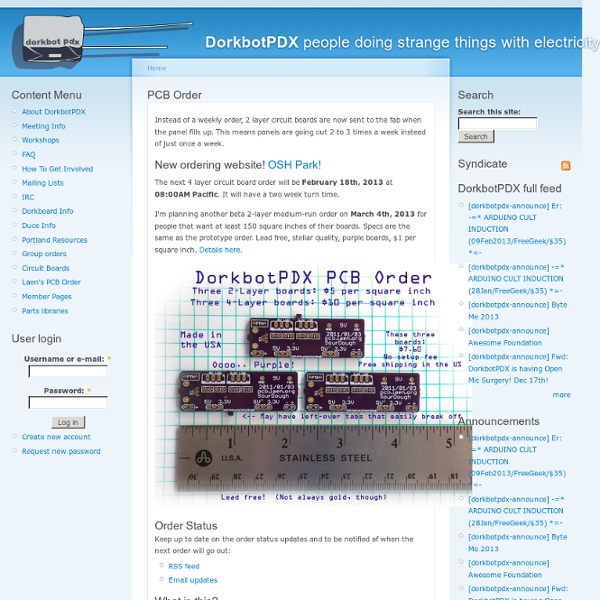
LED Video Wall | DorkbotPDX Several months ago, I was approached by the Portland band Starfucker (STRFKR) to build them an LED video wall for their upcoming tour. It needed to be large, bright, and durable, but also lightweight, portable, and easy to set up and tear down. They wanted to be able to plug in an iPod or iPad and play videos that are synced up along with their click track so everything goes along perfectly with the music. I enlisted the help of Alex Norman to take care of the software side of the project, and got to work trying to figure this thing out. It seemed like it could be made with mostly off-the-shelf components, and indeed that turned out to be the case. It didn't take long to find Adafruit's Digital Addressable RGB LED w/ PWM waterproof flexi strip, which looked like a good, simple solution for the pixels and drivers, since they all come together on a flex circuit and all you have to do is provide power and "SPI-like" data and clock signals. And here it is full-size:
MEMS Gyro-Accel | Gyroscope | Accelerometer | Processing - MPU-9250 The MPU-9x50™ family of parts are the world’s first 9-axis MotionTracking devices designed for battery operated, high performance consumer electronics products. The 9-axis product family incorporates the same market proven MotionFusion™ and run-time calibration firmware that is supported in InvenSense’s market leading MPU-6000 and MPU-3000 family of products. This firmware has shipped in millions of units and has been very well market validated. 9-Axis MotionTracking has become a key function in many consumer electronics devices including smartphones, tablets, gaming consoles, and smart-TVs. The MPU-9x50 devices combine a 3-axis gyroscope, 3-axis accelerometer and 3-axis compass in the same chip together with an onboard Digital Motion Processor™ (DMP™) capable of processing the complex 9-axis MotionFusion algorithms. The MPU-9x50 family is comprised of parts listed in the table below. MPU-9X50 System Diagram
9 Degrees of Freedom - MPU-9150 Breakout Description: The 9DOF MPU-9150 is the world’s first 9-axis MotionTracking MEMS device designed for the low power, low cost, and high performance requirements of consumer electronics equipment including smartphones, tablets and wearable sensors. And guess what? You get to play with it. This breakout board makes it easy to prototype with the InvenSense MPU-9150 by breaking out all the pins you need to standard 0.1" spaced headers. The board also provides I2C pullup resistors and a solder jumper to switch the I2C address of the device. The MPU-9150 is a System in Package (SiP) that combines two chips: the MPU-6050, which contains a 3-axis gyroscope, and 3-axis accelerometer. Features: Documents:
La fotoincisione dei circuiti stampati Torna alla Home Page Recapiti Introduzione Questo documento ha lo scopo di mettere a disposizione di chi lo desideri le tecniche necessarie ad ottenere con pochi mezzi la realizzazione di circuiti stampati mediante tecniche di fotoincisione. La qualità dei risultati ottenibili, pur non essendo ovviamente uguale a quella industriale, è davvero molto buona. In questa pagina descriveremo alcuni principi di base della fotoincisione, e descriveremo poi praticamente come realizzare un PCB. Per quanto riguarda il metodo di esposizione della basetta, diciamo subito che non è necessario disporre di un bromografo, di solito abbastanza costoso, a meno ovviamente di autocostruirlo; in questo articolo verrà infatti proposto l'utilizzo di una lampadina solare come sorgente luminosa, che, rispetto a un bromografo, necessita però di alcuni accorgimenti supplementari. Riconoscimenti Principi di base Realizzazione della maschera di layout b) Stampa inkjet su acetato (per inkjet) Esposizione Sviluppo
My Nixie Clock Project My Nixie Clock Project by Peter H. Wendt Rel. 0.9.5_en, Last Update: Wednesday, 2009-11-18 Most common question: "Your what Clock Project ?" Before Light-Emitting Diodes (LEDs) and Liquid Crystal Displays (LCDs) the electronic industry used cold-cathode tubes for displaying numbers, symbols and even characters. The animation below shows the button-like, top-viewed ZM1020. You got the idea, right ? Basically these Nixie tubes are very simple devices. If you apply a voltage Ub the voltage drops across the current-limiting resistor when one of the cathodes K0 - K9 is tied to GND. If your Ub is about 220 VDC a 47K resistor / 0.5 Watts will do for some testings. For a simplification we assume that the anode current Ia is equal to the cathode current Ik - you will have to tie only one cathode pin to GND at one time anyway. Some quick maths to calculate the values for the limiting resistor Ura = Ub - Ua -> 220 V - 140 V = 80 VDC Ra = Ura / Ia -> 80 VDC / 0.002 A = 40.000 Ohms Good question.
A Dozen Ways to Measure Fluid Level and How They Work December 1, 2004By: Kevin Hambrice, K-TEK Corp., Henry Hopper, K-TEK Corp. The demands of sophisticated automated processing systems, the need for ever-tighter process control, and an increasingly stringent regulatory environment drive process engineers to seek more precise and reliable level measurement systems. Improved level measurement accuracy makes it possible to reduce chemical-process variability, resulting in higher product quality, reduced cost, and less waste. Regulations, especially those governing electronic records, set stringent requirements for accuracy, reliability, and electronic reporting. The newer level measurement technologies help meet these requirements. Level Measurement Technology in Transition The simplest and oldest industrial level measuring device is, of course, the sight glass. Other level-detection devices include those based on specific gravity, the physical property most commonly used to sense the level surface. Established Level-Sensing Technologies r.
Telephone Interface (updated 12/30/09) This project describes an Arduino/MCU interface to a telephone land-line. It's only been tested on a US version of the telephone system, but hopefully it will apply to the phone system in other countries. The basic idea was to allow the MCU to make calls by transmitting DTMF tones, and to receive and decode DTMF tones (keystrokes) made on the phone that was called. There are other possibilities however. If you're only interested in sending and receiving DTMF tones and not interfacing to a phone line, you can skip the next dozen or so paragraphs. It all begins with the interface to the actual telephone line. There are two reasons for this: Phone lines require a 600 Ohm "balanced line". Lets start with #2. When you Google "phone interface" you'll be drinking from a fire hose of circuits, methods, and projects. For those who want to ignore points 1 & 2 above, here are some of the best resources I found, as well as the schematic for the "working" interface I was using. Enjoy
Telephone ringing circuits Copyright Tomi Engdahl 1997,2000,2005 Preface Telephone circuit gain always interrest, because telephones are everywhere and quite often there are old telephone luying around somewhere. Those telephones can be used for many interresting experiments including small home intercom: connect telephones in series or parallel and feed suitable operating current (about 20 mA) to them through resistor from power supply. The most problematic to home experimenter is how to get telephone ringing because the ringing voltage is over 50V and not at standard mains frequency (50/60Hz). Sometimes you want to get the information that telephone is ringing to your own circuits. What is ring signal ? The telephone company sends a ringing signal which is an AC waveform. The usual arrangement is to feed the 75 V a.c. ringing current (backed by earth) down one wire of the phone line. In USA minimum ring voltage supplied is 40Vrms (delivered into a 5 REN load). What is REN ? REN stand for Ringer Equivalen Number.
Free Download Electronic Circuit and PCB Layout Design Orcad 9.2 PSpice ~ ELTRONICSCHOOL Eltronicschool. - The popular electronic software that usually used for many electronic hobbies and student is OrCAD. This software also used for many electronic product design company around the world to make printed circuit board. Our experience we we using OrCAD software, with OrCAD software we can design and draw electronic schematic diagram using OrCad Capture and then we can continue to design Printed Circuit Board manually or auto-route using OrCAD Layout. When we want to create electronic circuit schematic or electronic wiring diagrams in OrCAD, we can open to work with OrCad Capture. We can draw electronic schematic in the window that provided with choose the components in the library. After chosen we can connect all the component according our electronic schematic using wire tool. And then after we draw the electronic circuit or electronic wiring diagrams, we can continue our work to make or create the PCB layout using Layout that provided by OrCAD software.