

Q factor vs bandwidth in octaves band filter -3 dB pass calculator calculation formula quality factor Q to bandwidth BW width octave convert filter BW octave vibration mastering slope dB/oct steepness EQ filter equalizer cutoff freqiency. BW = Δf = f0 / Q Q = f0 / BW f0= BW × Q = √ (f1 × f2)BW = f2 − f1 f1 = f02 / f2 = f2 − BW f2 = f02 / f1 = f1 + BW Conversion formula: 'octave bandwidth' N to quality factor Q: Conversion formula: Quality factor Q to 'octave bandwidth' N: Also known is this longer formula with 4 Qs; see its development at:Bandwidth in octaves versus Q in bandpass filters − RaneNote 170 Frequency ratio of an octave: Formula to convert quality factor Q to 'bandwidth in octaves' N, but with logarithmus naturalis:
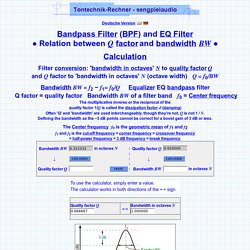
Q factor bandwidth in octaves filter conversion and converter - quality factor Q to bandwidth per octave width convert filter BW octave mastering. Low Pass Butterworth Filter Design Tutorial. Butterworth Filter Design In the previous filter tutorials we looked at simple first-order type low and high pass filters that contain only one single resistor and a single reactive component (a capacitor) within their RC filter circuit design.
In applications that use filters to shape the frequency spectrum of a signal such as in communications or control systems, the shape or width of the roll-off also called the “transition band”, for a simple first-order filter may be too long or wide and so active filters designed with more than one “order” are required. These types of filters are commonly known as “High-order” or “nth-order” filters. The complexity or Filter Type is defined by the filters “order”, and which is dependant upon the number of reactive components such as capacitors or inductors within its design. Then, for a filter that has an nth number order, it will have a subsequent roll-off rate of 20n dB/decade or 6n dB/octave. Decades and Octaves Logarithmic Frequency Scale. AMZ Stupidly Wonderful Tone Control 2. This design works quite well but has one limitation in that the high frequencies will always have some amount of attenuation because of the R1/C1 low pass network.
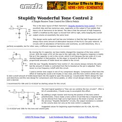
In circuits with an abundance of harmonics and overtones, as with distortions, this is perfecty acceptable, but for other uses, a different response may be needed. By moving the C1 capacitor, we have totally changed the response of the tone control circuit. With the wiper of R1 all the way to the right side, the frequency response is totally flat as if the capacitor is not in the circuit, which it isn't because the two ends of C1 are shorted together in that position. RC Filter and Time Constant Calculator. 'Isolator' Equaliser. Frequency 'Isolator' Equaliser Using State Variable Crossover© Rod Elliott, November 2014 PCBs will be made available for P148 (the basis for this project) if there is sufficient demand.
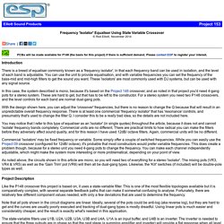
Please contact ESP to register your interest. Introduction There is a breed of equaliser commonly known as a 'frequency isolator', in that each frequency band can be used in isolation, and the level of each band is adjustable. You can use the unit to provide equalisation, and with variable frequencies you can set the frequency of the bass-mid and mid-high filters to get the sound you want. In this case, the system described is mono, because it's based on the Project 148 crossover, and as noted in that project you'd need 4-gang pots for a stereo system. Parametric EQ. Wien Bridge Based Parametric Equaliser© Rod Elliott (ESP) Introduction The main purpose of this article is to introduce the reader to a flexible equaliser circuit that can be used for hi-fi, mixing consoles, instrument amplifiers (especially bass guitar) or anywhere else that a simple and predictable 'parametric' equaliser is needed.
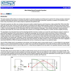
It's not perfect (I don't know of any circuit that is), but it is fairly simple to implement and performs well. Parametric equalisers are often very complex, because to enable variable frequency and Q requires a state-variable filter. While other filter types can also be used, most are not as well behaved or as flexible as the state-variable topology. Development Tools - FilterLab Filter Design Software. FREE filter design and analysis program. AADE Filter Design is FREE for download Version 4.0 added two new types of SSB crystal ladder filters described in an article " Modern Network Theory Design of Single-Sideband Crystal Ladder Filters, M.
Dishal, Proceedings of the IEEE December 1963" Version 4.11 adds the ability to store up to six sets of crystal parameters from your collection of crystals. That way you don't have to re-enter them everytime you want to design a crystal filter. Adds a little more to the crystal filter tutorial in the HELP file. 4.2 adds the ability for odd order Elliptic filters to have user specified input / output impedances that are different. 4.3 is an update to the HELP file. update is optional. 4.4 adds a "troubleshooting installation" item to the HELP menu No change to program so if yours works you don't need this. Since nobody seems to read the web troubleshooting information I have put it in the program as well. AADE Filter Design is now FREEWARE. My apologies to those who paid for it earlier. MITMAS_836S11_read02_bias.pdf. Active High Pass Filter - Op-amp High Pass Filter. Analog Filter Design—Wolfram Language Documentation.
TechnicalPres.pptx. Analog Filter Design Demystified. Abstract: This article shows how to design analog filters. It starts by covering the fundamentals of filters, goes on to introduce the basic types like Butterworth, Chebyshev, and Bessel, and then guides the reader through the design process for lowpass and highpass filters. Included are the derivation of the equations and the circuit implementation. It's a jungle out there. A small tribe, in the dense wilderness, is much sought after by head hunters from the surrounding plains. Known throughout the land for their esoteric expertise, this is the tribe of the Analog Engineers, who live in the farthest regions of the left half Plains, past the jungles of Laplace.