

DIY Audio Circuits - Schematics. KBápps.com - Home Page. Design And Build Your Own Tube Guitar Amp - WorkbenchFun.com. Design And Build Your Own Tube Guitar Ampby Kurt Prange Why Tubes?

If you’re not an electric guitar player or if you’re just starting out, you might ask why anyone would build anything with tubes. Aren’t vacuum tubes an obsolete technology? Well, yes and no. While tubes are no longer the technology of choice in the computer industry, they are very much alive and well when it comes to modern high-end guitar amplification. Guitar amps with tubes are currently front and center in the high-end market because many guitar players find their sound characteristics to be superior to solid-state amps (i.e. amps with transistors as the main active electronic devices).
DIY and the Boutique Amp Builder Boutique amp builders are individuals or small companies who build a relatively small number of amps each year with an emphasis on quality and attention to detail. Suggestions for a First Build Circuit Schematic Resource Links Happy building! Schematicheaven.com. Schematics » Hobby DIY Garage - Electronic Circuits Projects. Simple CD4046 VCO. Tips. Module Power Consumption Here is my spreadsheet with the power consumption of many purchased modules.
This information is from either the module specifications or was measured. Module power consumption spreadsheet Updated How To Get Started In Synth DIY People will look at my pages and then send me an email asking how to get started in Synth DIY. New Page 1. For you high-voltage minibooster fans out there, here's the one-chip, one battery way to do it.
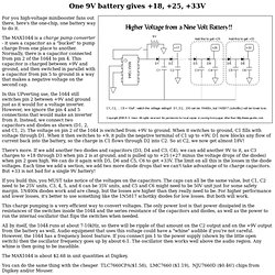
The MAX1044 is a charge pump converter - it uses a capacitor as a "bucket" to pump charge from one place to another. Normally, there is a capacitor connected from pin 2 of the 1044 to pin 4. This capacitor is charged between +9V and ground, and then switched in parallel with a capacitor from pin 5 to ground in a way that makes a negative voltage on the second cap. In this UPverting use, the 1044 still switches pin 2 between +9V and ground just as it would for a voltage inverter. Www.geofex.com/Article_Folders/Power-supplies/powersup.htm. When you get tired of paying for batteries for your effects, you start thinking about getting a wall wart to run your effects.
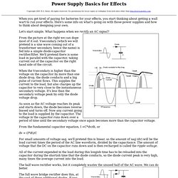
Here's some info on what's going on with those power supplies and how to think about designing your own. Let's start simple. What happens when we rectify an AC signal? From the picture at the right we can dope most of it out. Www.musicfromouterspace.com/analogsynth_new/WALLWARTSUPPLY/WALLWARTSUPPLY.php. Wall Wart Power Supply (+/-9V to +/-15V) Article by Ray Wilson This is an intermediate to advanced project and I do not recommend it as a first project if you are just getting started in synths or electronics.
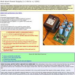
Only the circuit and some explanation are shown here. A lot of project building, troubleshooting and electronics experience is assumed. Www.geofex.com/Article_Folders/Power-supplies/powersup.htm. Www.musicfromouterspace.com/analogsynth_new/WALLWARTSUPPLY/WALLWARTSUPPLY.php. John Hollis - Assorted Circuit Designs. Brass BlenderSCH.jpg (1024×526) The Brass Blender. Here is a totally different version of the ParaLooper.
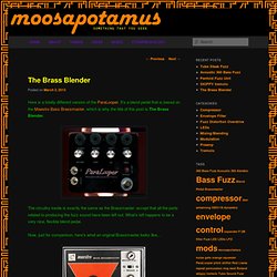
It’s a blend pedal that is based on the Maestro Bass Brassmaster, which is why the title of this post is The Brass Blender. The circuitry inside is exactly the same as the Brassmaster, except that all the parts related to producing the fuzz sound have been left out. Fsh1asc.gif (1235×1465) Circuit Snippets. Circuit Snippets Back to Main Page Listen to The Gargletron Listen to The Pushme Pullyou Listen to The Tripple Fuzz Listen to the Cinnabar Listen to Phuncgnosis Listen to sample of the T.M.K.
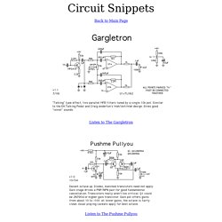
Listen to sample of the Simple Square Wave Shaper. John Hollis - Assorted Circuit Designs. LM13600/LM13700. A Short Discussion of the Operational Transconductance Amplifier (OTA) In the late sixties, RCA, then one of the major leaders in linear semiconductors, came out with the Operational Transconductance Amplifier, hereafter called OTA.
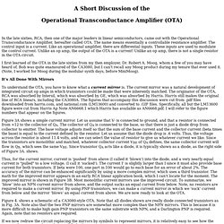
The name means essentially a controllable resistance amplifier. The control input is a current. Like an operational amplifier, there are differential inputs. I first learned of the OTA in the late sixties from my then employer, Dr. Mojo ICs » LM13600 Dual Operational Transconductance Amplifiers with Linearizing Diodes and Buffers. HC CH. Ch Mods for Deluxe Electric Mistress I really dont know why people are slanting down the sound of the deluxe version of mistress, I like it a lot.
Specially after these little mods!! The polarity switch makes it sounda kinda phaser-like. Then I took out the delay-time trimpot and moved it to the front as a pot. Ch Octave Divider This is little something I built few years back. Schematic isn't exactly the one I made, but this should work. The ValveLiTzer: Low-voltage Tube Booster. Vacuum tubes have an interesting characteristic called "starved cathode" operation, which results in a good deal of distortion when the tubes are run at very low voltages.
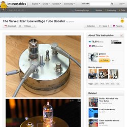
Matsumin's Valve Caster tube booster was my introduction to low-voltage tube projects. Kit Review: The Persuader Tube Drive Pedal - GuitarKitBuilder. The Persuader is a tube-drive distortion pedal kit sold by Amplified Parts of Tempe, AZ. Amplified Parts is a relatively new entity that is part of Antique Electronic Supply, which has been operating for more than 25 years. The focus of Amplified Parts is on the musician who is not an electronic technician and who wants to create his/her own sound or tone by modifying their existing amplifier or guitar.
Guitar Kit Builder received one these kits to review, and we gave it to Casey4s to build and try out. Before we get into his review let’s cover the basic circuit design as shown in the schematic below (click on the circuit for a larger pdf version).The Persuader Schematic. Ring Modulator Kit, Electronic Projects for Musicians, CA-9. Viva-analog.com. \\\ Original Analog Bass/Guitar Effects and DIY /// Custom/Original Designs JC Maillet (c) 1996-2010 High Precision Rectifying Octaver JCM(c)2010 Stereo Guitar/Bass Fuzz with Presence and Blend Updated Sampler with Effective Clock Nulling. On negative resistance - 04/07/00. The Negistor & Negative Resistance - 04/07/00 courtesy Marcelo Puhl The following information is with regard to negative resistance as has been discussed on the KeelyNet Interact discussion as posted on the eScribe KeelyNet public archives. Some of the relevant files deal with early germanium point contact transistors which had negative resistance properties as pointed out by Tom Bearden.
You might want to read some of the discussion list comments and URLs below; Initial query on how to test for 'negative resistance'. Welcome To. Breadboard A Vintage Distortion. Breadboard A Vintage IC Distortion 2010 By Small Bear Electronics LLC My How-To on Breadboarding A Silicon Fuzz Face got a very good response, and some of the people who liked that piece asked me to do something similar for an IC-based distortion--maybe similar to an MXR Distortion + or a BOSS DS-1.
Sounded like a fine idea! If you have never used a solderless breadboard, please refer to the intro article before you continue on here. That How-To covers a lot of basic information and techniques; I presume that you have been through it, have done the demos, understand how the tool works and have started learning to use your multimeter. For a demo at this level, I thought the MXR Distortion + a little too easy.
Here's the basic circuit that we will set up: Links. This article answers some common questions about the transistors used in cloning and modifying the Fuzz Face and similar pedals. It is meant for beginners who are confused about what devices to use and where to get them, and as a reference for more experienced DIYers. I wrote it in 2000 when I first began offering matched germanium transistors. I have updated it many times since to reflect things I've learned and changes in the old-stock transistor market. What transistor types are best suited for the FF?
They should be germanium if you want to get the classic 60's/70's "soft" distortion. Germanium Darlington Pairs. HC CH. \\\ Original Analog Bass/Guitar Effects and DIY /// Fx projects. Moosapotamus. A Shining Light – The Gift of Knowledge. Moosapotamus. Conductive Glue And Conductive Thread: Make an LED Display and Fabric Circuit That Rolls Up. To make your own conductive glue, you will be taking an insulator (Liquid Tape rubber or DAP Contact Cement) and turning it into an electrical conductor.
This is done by the addition of carbon graphite powder which is a conductor. As the binder (LT or DAP) sets up, the carbon crystal flakes stack on each other and intertwine to make the glue conductive. The result is a flexible conductive glue that will stick well to most things. The glass circuit doodle in pic3 below, is used to illustrate some of the ways the different glues can be used. Click on the comment squares for details. DIY Tips - How Guitar Pickups Work. Arduino Sequenced Wah Guitar Effect. The Big Picture. Metal film resistor » Resistor Guide. Metal film resistors. HC CH. Circuit Snippets.
John Hollis - Assorted Circuit Designs. Moosapotamus. Dave Mac's Window on the World. Synthgeek's blog » amplifier. September 2010. Other. September 2010. Guitar & Bass Wiring Modifications & Diagrams. Guitar Parts & Wiring Diagrams-FREE Shipping Over $49. Ampeg Scrambler. Ampeg Scrambler The Wild Octaver This is the clone of the very rare Ampeg Scrambler, which was built in very small numbers back in the late 60s. Originals are very rare these days and sell of outrageously high prices when one does become available, similar to the Tycobrahe Octavia. Audio calculations in English - acoustics calculator convert audio formulas sound calculations microphone formula sound recording studio useful stuff free audio calculator recording studio acoustic audio engineering site map online education sound calcs e.
RED Free Circuit Designs - Audio. College Instrumentation Specialist - NEETS. Topopiccione Electronics Inc. - Main Page. Fix for a Linear taper Pot « JT30 – Amplified Blues Harmonica. One of the big problems with working with high impedance mics is that a volume control potentiometer must be large enough to match both the element impedance and the input impedance of the amplifier.
Volume control pots for high impedance mics feeding tube amps should be larger than 100K ohms and a 1-meg pot is a common value. "EVITA" - electronic components, parts, radionics. Search & inquiry. Echo Bender V2. Russian transistors - "EVITA" A quality tone control circuit using opamp and few passive components. The 071 Family. Monk Soundworks. "Noise Ensemble" - simple PT2399 abuse! Echo Bender V2. DIY Audio Circuits - PT2399 Digital Delay Analog Echo IC. The Secret Life of Pots. 3 Channel Spectrum Analyzer - circuit diagrams, schematics, electronic projects. Project 136. Electronic Boy for You. AMZ - Guitar Effects & reverse transistor beta. AMZ Guitar Effects Schematics. Fattening the Tone in a Vintage Vox Wah Pedal. Dunlop GCB-95 "FatWah" Mod. Merch. TRANSISTOR BIASING 2 by Harry Lythall. Simulation Tools for amateurs. Electronoize Playshop: 40106 Oscillator. Capacitor Code Information.
TRANSISTOR BIASING 2 by Harry Lythall. THE SIMPLEST 555 OSCILLATOR Circuit. Beginners Guide. TALKING ELECTRONICS Page 39. Parts explanation of Radio Controlled Clock. The Technology of Wah Pedals. Building a Wah Pedal From Scratch #2. Effectrode builds a range of pedals that utilize miniature and NOS Mil-Spec subminiature tubes with modern audio-grade components. Www.DIYguitarist.com Home Page. The Technology of Wah Pedals. Electronoize Playshop: 40106 Oscillator. Craig Anderton's Volume Pedal De-Scratcher. Holtek echo.gif (1435×1080) Heterodyne-Peyote-Space-Explorer.jpg (847×1267) Excellent Tutorial on Building Logic IC Oscillators from Beavis Audio Research.
Delay-Modulation. Guitar Effects Pedals, Schematics, Stompboxes & Electronic Projects. General Guitar Gadgets.